In centrifuges, a centrifugal force, generated by high-speed rotations, is used to separate solids from liquids. Centrifugation can be used to recover solids from slurries to clarify liquids, or to clarify solids.
Centrifuges can be categorized as either sedimentation or filtration units. Sedimentation centrifugation units rely on the density difference between the solid and liquid separated. As the slurry enters the spinning centrifuge, it forms an annulus next to the bowl wall. Because of the centrifugal force, the denser material moves outwardly toward the wall of the centrifuge bowl. At the same time, the liquid overflows from the bowl or is picked up by a skimmer. Quite often, the solid must be removed from the centrifuge manually or with a cutter knife. It can also be removed continuously with a screw conveyor. On the other hand, filtration centrifuges filter the material with a rotating basket fitted with a filter medium, where the centrifugal force of rotation expels the liquid through the filter.
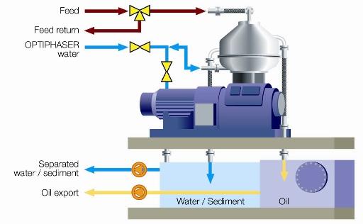
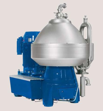
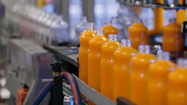
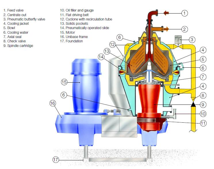
Shown below is an example of an industrial process that uses a disk centrifuge to separate oil, water, and sediment.
Simple
Laboratory
General Information
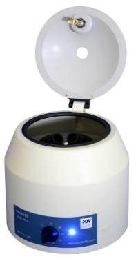
The most basic laboratory centrifuge is a test-tube centrifuge. Test tubes are placed in a holder, the lid is closed and the tubes are spun. The resulting centrifugal force causes the denser components to move to the bottom of the tube, with the less dense components above them.
Laboratory centrifuges are used primarily to separate small amounts of mixtures, such as cell extracts. They are also heavily used in process development.
Advantages
- Can be used to separate very small amounts of mixtures
- Small size lends to ease in placement within the workspace.
Disadvantages
- Small capacity.
Basic
Tubular-Bowl
Tubular-bowl centrifuges are sedimentation centrifuges. They can be used to separate both solid/liquid and liquid/liquid mixtures.
General Information
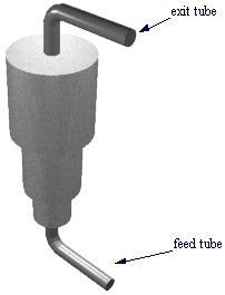
In tubular-bowl centrifuges, feed enters from the bottom of the cylindrical bowl. A distributor and baffle assembly accelerate the incoming liquid to rotor speed. Then, a baffle separates the feed into its components (two liquid layers for liquid/liquid separations, or solid and liquid layers for solid/liquid separations). The outer layer, which consists of the heavier components, becomes concentrated against the wall, while the inner layer, which consists of the lighter components, floats on top.
Each layer then travels up the side of the bowl as an annulus. Liquid layers are discharged through overflow ports located on the top of the centrifuge. Solid buildups remain in the bowl and are recovered manually.
Equipment Design
Tubular-bowl centrifuges generally consist of a bowl, a motor, and a drive assembly. The bowl is suspended from an upper bearing and hangs freely. This allows the bowl to find its natural axis of rotation if it becomes unbalanced.
The discharge ports at the top of the bowl are located at different radii and elevations depending on the properties of the components to be separated. The picture below shows the upper bearing suspending the bowl as well as a discharge port.
The inner bowl in tubular-bowl centrifuges can range in capacity from 1 to 15 gallons, and can handle up to 1200 gal/hr of feed. Tubular-bowl centrifuges can be outfitted with a knife discharge system, which mechanically removes any built-up solids within the bowl. Shown below is the feed inlet into the bowl of a tubular centrifuge.
Usage Examples
Tubular-bowl centrifuges have a wide range of uses in industry. A typical application is the purification of lubricating industrial oils containing 1% or less of sedimentable solids.
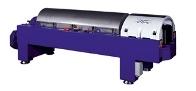
Tubular-bowl centrifuges also see much use in the food, biochemical, and pharmaceutical industries. The picture below to the left is an example of a laboratory-scale tubular centrifuge that is powered by a single-phase motor. These centrifuges can be powered with electric motors, steam turbines, or compressed air. The picture to the right is an example of a tubular centrifuge used in industry.
Advantages
- Can be used for both liquid/liquid and solid/liquid separations
Disadvantages
- Foaming of liquids may occur
Continuous
Continuous Decanter
Continuous decanter centrifuges contain a helical screw to remove solids from the bowl.
General Information
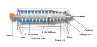
Continuous decanter centrifuges have a solid wall bowl with either a vertical or horizontal axis of rotation. Feed enters the bowl through a concentric tube. The liquid phase (arrows) migrates to the larger radius end of the bowl where it is discharged continuously, while the solids (red spheres) are continuously transported to the other end of the bowl by a helical screw conveyor.
Equipment Design
Continuous decanter centrifuge bowls can be conical, cylindrical, or a combination of the two. The solids discharge ports at one end are usually smaller in radius than the liquids discharge ports at the other end. The helical screw conveyor runs the length of the bowl. Flocculating agents may be added to the centrifuge to collect softer solids. A flocculating agent is a substance that causes soft solids to congeal into small masses.
(Copyright Alfa Laval, Richmond, VA)
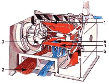
Another example of a continuous centrifuge is the pusher centrifuge. These are used to separate coarse solids from slurry mixtures. In order to do this, the slurry is deposited on the feed screen where liquors drain through and solids collect (1 and 2 in the diagram below). Next, the pusher plate moves the solid film forward, exposing more usable screen space. As the film cake dries, more liquor can be sprayed to remove more impurities. Finally, after the cake has dried it can be pushed out the discharge for further processing, (3-6 in the diagram below).
Usage Examples
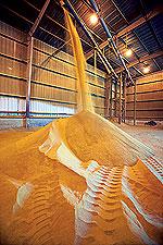
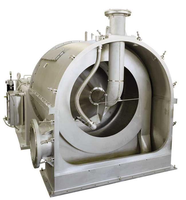
Continuous decanter centrifuges are most typically used for processes in which continuous production is required, such as purifying used lubricating oils. Corn used to make ethanol is shown below, to the left. Ethanol producers use centrifuges in the production of ethanol from corn. The picture to the right is an example of an industrial pusher centrifuge used to separate coarse solids from crystalline slurries continuously with minimum preventive maintenance.
Advantages
- Can be used continuously, eliminating cleaning time.
Disadvantages
- Mechanically complex.
Screen-Bowl
General Information
As seen in the animation below, screen-bowl continuous decanter centrifuges consist of a solid bowl to which a cylindrical screen has been added. The bowl and the screen rotate, creating a centrifugal force. Feed is introduced into the large portion of the bowl, where the centrifugal force presses it to the edge (top and bottom) of the bowl. A helical screw conveyor transports the solid component (yellow) to the small end of the bowl. As the bowl diameter decreases, the solid component is raised above the water line (blue). As the solid component passes over the screen, any remaining liquid exits through the screen. The bulk of the liquid component flows back over baffles, and out the large end.
Equipment Design
The screen portion of screen-bowl continuous decanters provides additional time for the solids to drain under centrifugal force. This additional step improves separation.
Self-Opening
General Information
As their name implies, self-opening centrifuges are able to open during operation to discharge solids. Feed enters the bowl from the bottom, is exposed to centrifugal force, and separates into its components. When the desired amount of solids has accumulated, a sleeve inside the bowl opens and the solids are discharged radially outward. The schematics below show the sleeve in open and closed positions.
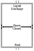
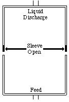
Equipment Design
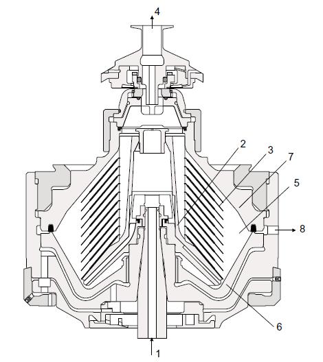
The sleeve in self-opening centrifuges is kept closed by static pressure induced by hydraulic fluid. When the pressure decreases, the sleeve is allowed to open, exposing an anular, ring-like, area through which solids are discharged. An elastomeric seal around the top of the bowl ensures that there is no leakage while the sleeve is closed. Self-opening centrifuges can typically handle up to 220 gal/min of feed. The diagram below is of a typical self-opening centrifuge. The feed enters from the bottom (1) and the solids are separated through the disk stack (3) and collect in the periphery. The hydraulic system forces the bowl bottom (6) to drop down, opening the ports on the side (8), and allowing the solids to discharge.
Multi-Chamber
General Information
The bowl of multi-chamber centrifuges consists of a series of short tubular sections of increasing diameter linked together to form a continuous tubular passage. Feed is introduced into the smallest diameter tube first and progresses through outer tube diameters as they increase in size. Typically, up to six chambers are connected.
Since the centrifugal force increases as the diameter increases, the heavier particles will be deposited in the smallest diameter tube.
Usage Examples
Multi-chamber centrifuges see much use in the food industry. They are used to clarify fruit juices, wort, and beer.
Advanced
Disk
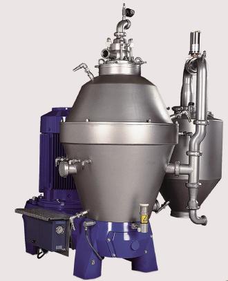
Disk centrifuges are the most commonly used centrifuges in industry. The disk centrifuge below is commonly used in the brewing industry.
General Information
Feed is introduced into a disk centrifuge from the center of the bowl near its bottom. The feed then rises through a stack of disks. Each disk has numerous holes, which form flow channels when the disks are stacked.
The liquid portion of the feed flows through these channels, while the solids collect on the disks’ surface. Centrifugal force causes the solids to move outward from the center of the disk toward the wall of the bowl, where they collect.
Equipment Design
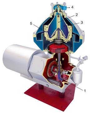
A typical disk centrifuge stack contains 100 or more disks. The disks reduce the distance that a solid particle must travel before it is separated from the feed. Disk centrifuges range in diameter from 102-762 mm, and are capable of creating forces up to 14,000 times that of gravity. The two diagrams below show how disk centrifuges work. In the first diagram, the feed enters through the bottom and accelerates up through center of the bowl. As the bowl spins the solids separate through the disks and collect on the outside of the bowl. The liquid continues out through the top and the solids can be collected from the periphery. In the second diagram the feed enters through the top and separates through the disks. The solids form pockets recessed on the sides of the bowl. The solids then flow through axial discharge valves to be collected.
Usage Examples
Disk centrifuges are typically used in separations in which the percentage of solids in the liquid feed is small, such as cream separation and the concentration of butterfat milk. Shown below are examples of disk stack centrifuges. The centrifuge on the right is used to clarify liquids from shear-sensitive particles. The centrifuge on the left is used to refine oil and fat.
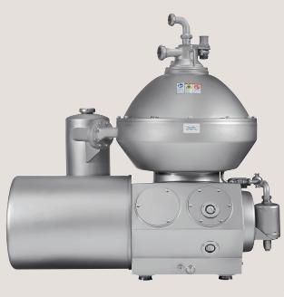
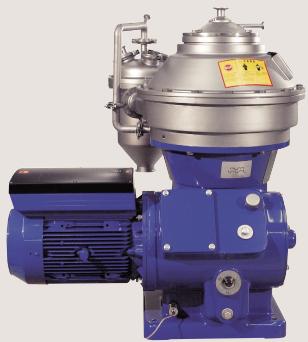
(Copyright Alfa Laval, Richmond, VA)
Advantages
- Can be used for both liquid/liquid and solid/liquid separations
Disadvantages
- Downtime for cleaning lowers efficiency
- Can only be used for feeds with small solid content
Nozzle-Discharge
General Information/Equipment Design
The animation below shows a nozzle-discharge centrifuge. In nozzle-discharge centrifuges, the solids are continuously discharged through nozzles located around the periphery of the bowl and are collected in a surrounding basket (not shown).
(Animation based on a schematic copyright Alfa Laval, Richmond, VA)
Nozzle diameters range from 0.6 mm to 3 mm and are typically twice the diameter of the largest particle to be separated. Nozzles are arranged around the bowl so that they are directed tangentially backward to the direction of rotation. This serves two purposes: recovery of kinetic energy and reduction of motor power requirements.
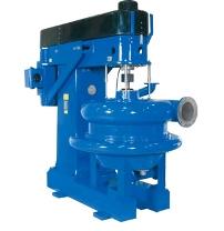
Shown below is an example of a nozzle-discharge centrifuge that is designed to handle high solid loads.
Advantages
- Continuous operation results in faster separations.
Disadvantages
- Solids may build up, causing a decrease in clarification efficiency.
- Prescreening may be necessary to weed out particles too large to fit through the nozzles.
Acknowledgements
- Alfa Laval, Richmond, VA
- B&P Process Equipment , Saginaw, MI
- Lab Essentials, Inc., Monroe, GA
References
- Letki, Alan G. “Know When to Turn to Centrifugal Separation.” Chemical Engineering Progress. September 1998: 29-44.
- McCabe, Warren L., Julian C. Smith, and Peter Harriott. Unit Operations of Chemical Engineering. 5th ed. McGraw-Hill, New York, 1993. Print.
- Perry, Robert H., and Don W. Green. Perry’s Chemical Engineers’ Handbook, 7th ed. New York: McGraw Hill, 1997: 18-106 – 18-125. Print.
- Rousseau, Ronald W. Handbook of Separation Technology New York: John Wiley & Sons, 1987: 163-167. Print.
- Schweitzer, Philip A. Handbook of Separation Techniques for Chemical Engineers. 2nd ed. New York: McGraw-Hill Inc., 1988: 4-59 – 4-88. Print.
- Svarovsky, Ladislav. Solid-Liquid Separation. 3rd ed. Boston: Butterworths & Co., 1977: 260-273. Print.
- Torzewski, Kate. “Facts at your Fingerprints: Sedimentation Centrifuging”. Chemical Engineering. January 2008: 27.
Developers
- Sam Catalano
- Joseph Palazzolo
- Matthew Robertson
- Steve Wesorick
- Abigail Nalbandian
- Keith Minbiole