Compressors are used to increase the pressure of a fluid. The main type of compressor is the rotary compressor, meaning a rotary device is used to compress the fluid. Reciprocating and centrifugal compressors are the most common.
Rotary
Sliding Vane
Sliding vane compressors are widely used as vacuum pumps as well as compressors.
General Information
The sliding vane compressor is a rotary type compressor, meaning a rotating device is used to compress gas. Vanes on the rotor trap gas between the rotor and cylinder walls. This gas is compressed and released into the discharge line.
Equipment Design
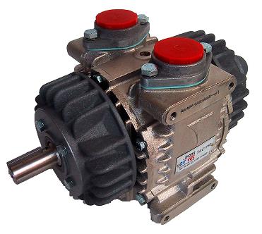
The sliding vane compressor consists of a rotor mounted off-center in a cylinder slightly larger than the rotor. The rotor has a series of radial slots that hold vanes. These vanes are free to move in and out of the slots, but always maintain contact with the cylinder wall. The diagram below shows a cutaway view of a sliding vane compressor.
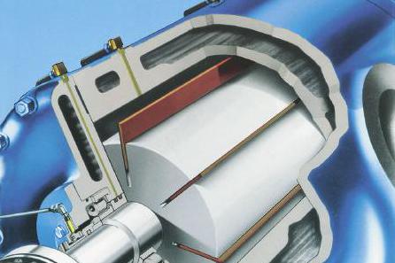
As the rotor turns and a pair of vanes approach the inlet, gas begins to fill the cell. As the rotation continues, the suction edge is passed by both of the vanes, sealing the cell of gas. The suction edge is the point where the vane first touches the cylinder wall. The vanes are pushed back into the rotor by the eccentricity of the cylinder wall. This decreases the volume of the gas cell, increasing the pressure of the contained gas. The compression continues throughout the rotation until the leading vane crosses the discharge port, releasing the compressed gas into the discharge line.
Usage Examples
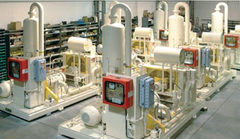
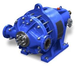
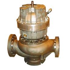
Sliding vane compressors are versatile, finding applications in areas such as gas boosting, vapor recovery, and enhanced oil recovery. The gas compressor pictured below is used in biogas digester applications.
Advantages
- Lightweight machine
- Versatile
Disadvantages
- Low efficiency compared to reciprocating compressors
Screw
Screw compressors are also called helical-lobe compressors.
General Information
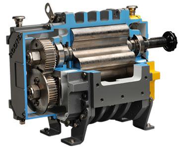
Screw compressors are positive displacement, intermittent, rotary compressors. This type uses two intermeshing lobes to compress gas, such as those shown in picture below.

Oil-Injected Screw (OIS) compressors inject oil into several key areas of the compressor to provide lubrication, sealing, cooling, corrosion inhibiting, and noise dampening. The choice between OIS and Oil-Free Screw (OFS) compressors depends on the specific process requirements and tendencies.
Equipment Design
Screw compressors use the intermeshing of two rotors in the form of a helix. The male rotor has four convex lobes, the female rotor has six concave flutes like the ones shown above. Gas enters at the inlet port when the volume between the two is at its maximum. As the rotor turns, a lobe from the male rotor progressively enters the flute of the female rotor, decreasing the volume between the lobes and thus compressing the gas. The rotation of the rotor continues until the discharge port is reached, releasing the compressed gases.
An oil-separation system and a lubrication system are used with oil-injected screw compressors. The oil-separator utilizes wire mesh demister devices for the separation of oil that gets into the gas and has a smaller storage tank to hold the separated oil. Sizing of the compressor is based on flow demand and pressure requirements.
Usage Examples
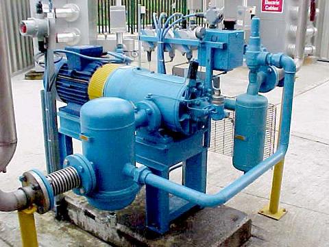
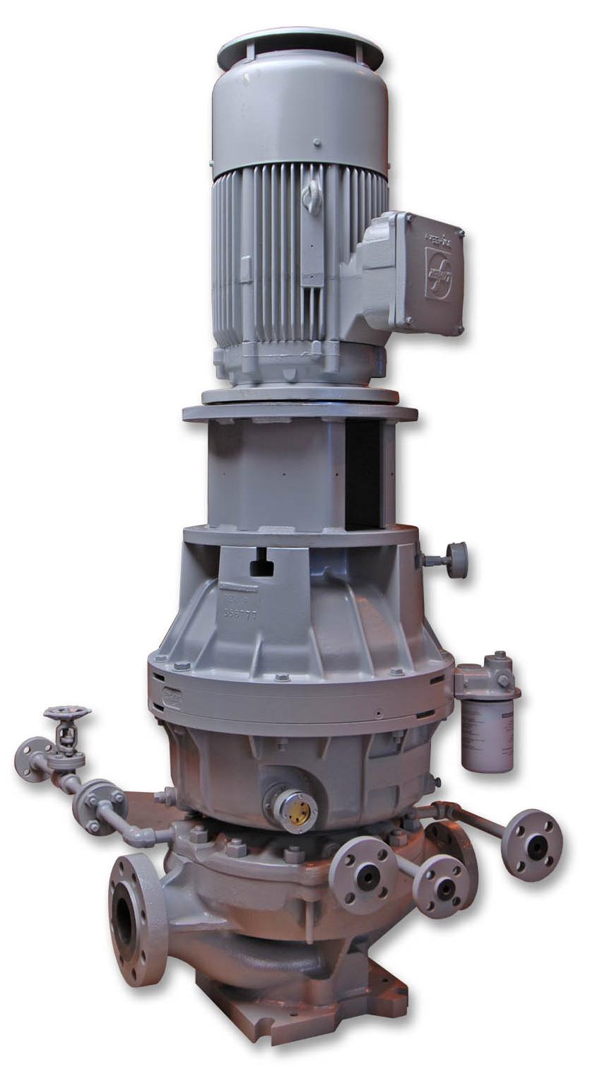
Screw compressors are used for applications requiring pressures between those produced by reciprocating compressors and centrifugal compressors. Originally, screw compressors were primarily used in the petrochemical industries. Today, most applications are in air and refrigeration services, and fuel gas markets. The rotary screw compressor pictured below is used to compress helium for industrial applications.

Advantages
- Ideal for applications with moderate flow rates and medium discharge pressures (pressures between those produced by reciprocating and centrifugal compressors)
- Liquid entrainment is easily flashed off
- Low maintenance required
Disadvantages
- Decreased efficiency if operated at a pressure ratio other than the designed pressure ratio
- Auxiliary components are expensive
Liquid Piston
General Information/Equipment Design
Liquid piston compressors perform compression with the use of a liquid ring acting as a piston.
Like sliding vane compressors, this type has a rotor mounted off-center in a cylinder. Forward curved vanes are attached to the rotor. A liquid compressant partially fills the cylinder, forming a ring of liquid on the inside wall of the cylinder. Because the rotor is off-center, the volume between the ring and the rotor varies. This volume is maximum at the inlet port, where a pocket of gas enters. As the rotor turns, the gas is carried with it. As the volume between the liquid ring and the rotor decreases, the liquid acts as a piston, compressing the trapped gas. This gas is then released at the discharge port.
Advantages
- Operation is not affected by the intake of liquid
Disadvantages
- Low efficiency
Straight Lobe
General Information/Equipment Design
Straight lobe compressors have two rotors that intermesh as they rotate. These rotors usually have two lobes, although three lobe compressors are available, such as in the compressor pictured below.
Gas is trapped and carried between the lobes as they pass the inlet port. The lobes push the gas toward the exit. Compression occurs due to the backpressure of the gas in the discharge line.
Advantages
- No internal gas compression
Disadvantages
- Limited pressure range
Other
Reciprocating
Reciprocating compressors are the most widely used type of compressor.
General Information
Reciprocating compressors are positive displacement, intermittent compression devices analogous to a typical bicycle pump. Gas enters a chamber controlled by a piston. Pushing the piston down reduces the volume of the gas, causing an increase in pressure. This high-pressure air is then pushed out of the chamber.
Equipment Design
The cylinder begins the cycle filled with gas at the intake pressure. The piston strokes inwards, decreasing the volume of the cylinder and therefore increasing the pressure. Once the desired pressure of the gas is reached, the discharge valve opens, and the piston pushes some of the high pressure gas out. At the end of the stroke, the piston reverses direction. Once the pressure of the remaining gas in the cylinder is the same as the intake pressure, the intake valve opens, refilling the cylinder.
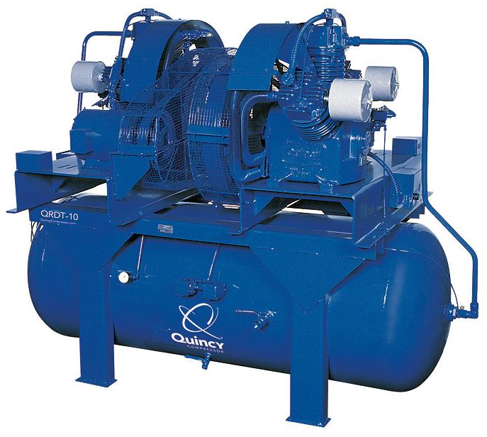
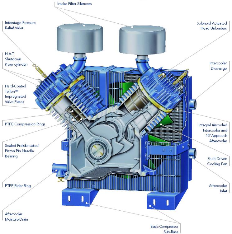
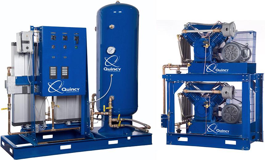
Reciprocating compressors consist of a single cylinder or multiple cylinders on a frame. Inside the cylinders, pistons reciprocate, compressing the gas. Single-stage compressor consist of a single cylinder or multiple cylinders in parallel. A multistage compressor consists of multiple cylinders in series. Cooling water is used so that the energy dissipated from the compressor can be evacuated to the water. Below is a labeled diagram of a double-stage compressor.
Usage Examples
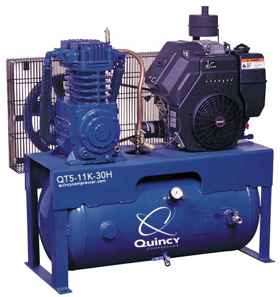
Most reciprocating compressors are used to generate pressurized air. The compressors shown below are used to pressurize air in healthcare facilities. The most common applications in refineries are hydrogen-rich streams, refinery fuel gas, and refrigeration systems.
Advantages
- Especially useful for low to moderate flow rates, low molecular weight gases, and high required discharge pressures
- Easily multi-staged
Disadvantages
- Low capacity
- Low reliability due to many wearing parts
- High maintenance required
- Little flexibility in material choices
- Pulsation and unbalanced forces created by reciprocating motion
Centrifugal
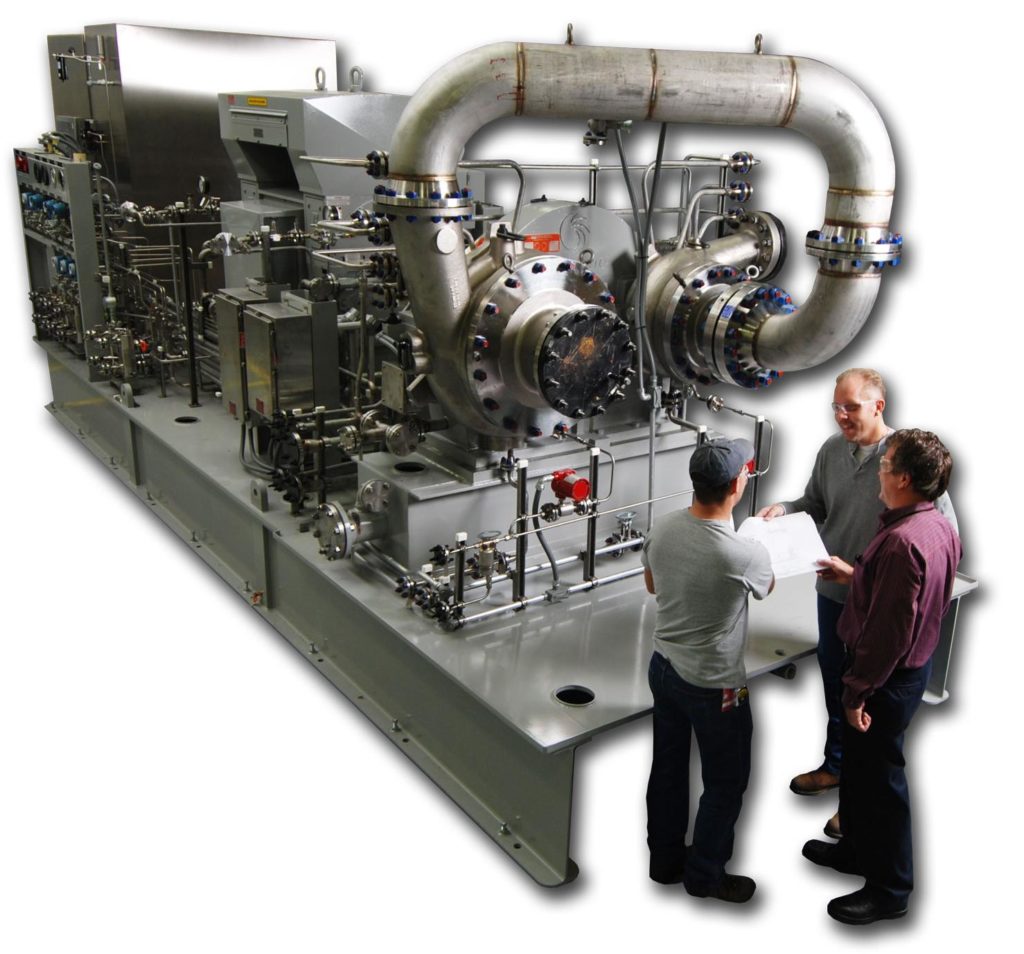
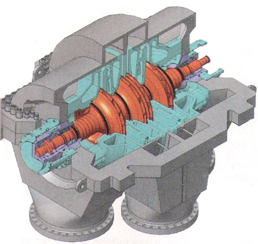
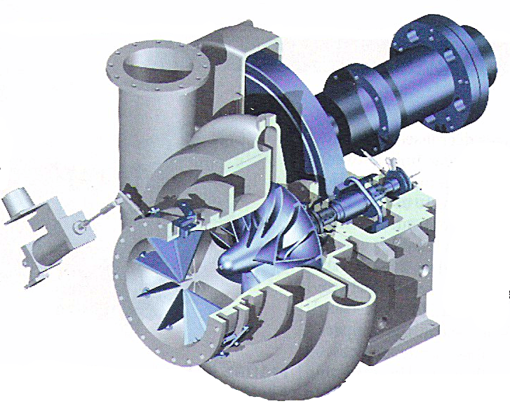
Centrifugal compressors are widely used, second only to reciprocating compressors in a number of machines in the process industries because of their size and ease of use. Shown below is an integrally geared, multistage centrifugal compressor.
General Information
Centrifugal compressors are dynamic compressors, meaning energy is transferred from a moving set of blades to the gas. This energy takes the form of velocity and pressure.
Equipment Design
Centrifugal compressors use an impeller consisting of radial or backward bending blades. As the impeller rotates, the gas between the rotating blades is moved from the area near the shaft radially outward into a diffuser. Energy is transferred to the gas while it is travelling through the impeller. Some of the energy results in an increase in pressure, and some contribute to the velocity of the gas. This velocity decreases in the diffuser, resulting in higher pressure and compression of the gas.
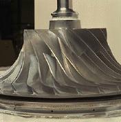
Centrifugal compressors are often built in a multistage configuration (shown below to the left), where several impellers are installed in one frame and operate in series as shown in the animation below. In a single-stage centrifugal compressor (shown below to the right) one impeller is used and is often overhung. The air pressure increases (arrows in animation get darker) after each impeller, allowing the multistage compressor to obtain higher pressures than a single-stage compressor. Both types of centrifugal compressors can also be modified to admit or extract vapor from or to side streams with the use of strategically placed nozzles. Centrifugal compressors are dynamic compressors, meaning energy is transferred from a moving set of blades to the gas. This energy takes the form of velocity and pressure.
The compressor shafts are made from low-alloy steel or sometimes from corrosion-resistant materials. Most impellers are also made from low-alloy steel and come in two types: a closed impeller and a semi-open impeller. In closed impellers the blades and hubs are covered while in semi-open, often called open, impellers the impellers are not covered. Closed impellers can reach maximum allowed speeds of 310 m/s and semi-open impellers can reach 400 m/s.
Usage Examples
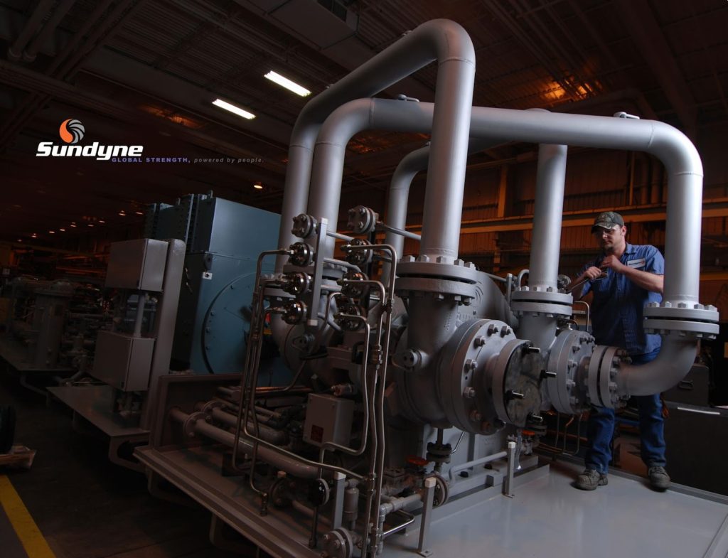
Originally, centrifugal compressors were used exclusively in steam turbines, but now they have also used in process plants as well as natural gas and petrochemical plants. The multistage compressor shown below is used to recycle hydrogen in an oil refining process.
Advantages
- Useful for large flows, high molecular weight gases, and high pressures
- Large flows can be compressed with high-pressure capability
- High reliability
Disadvantages
- Limited choice of pressure ratio
- Large energy consumption
- High repair cost
- Low efficiency
Axial
General Information/Equipment Design
Axial compressors are high-speed, large volume compressors in which gas flows axially through the machine. They are typically used for high flow and relatively low pressure applications.
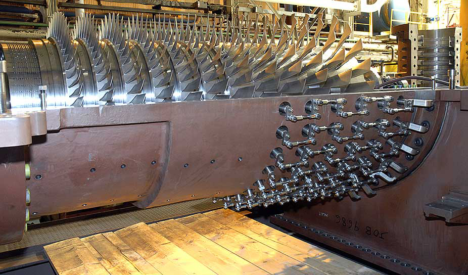
The energy from the rotor is transferred to the gas by rows of rotating blades (blue). The rows of blades alternate with stationary sections called stators (red). The gas enters through the first stator, referred to as the guide vane row, and is acted upon by the rotor. The gas exits to the next stator row and continues in the axial direction alternating rotor and stator rows. As the gas travels through the compressor, its pressure increases (arrows get darker), resulting in compression.
Advantages
- Very high efficiency
- Highly sophisticated compressor
Disadvantages
- Very expensive
Acknowledgements
- Chemical Engineering, Access Intelligence, LLC
- Elliot Group, Jeannette, PA
- FLSmidth Inc., Bethlehem, PA
- Gardner Denver Nash, Trumbull, CT
- GE Energy, Houston, TX
- Kaeser Compressors, Inc., Fredericksburg, VA
- NASA Glenn Research Center
- Quincy Compressor, Quincy, IL
- Ro-Flo Compressors, LLC, Appleton, WI
- Sundyne Corporation, Arvada, CO
- Transairvac International Ltd, Staffordshire, England
References
- Almasi, Amin. “Centrifugal Compressors for CPI Plants.” Chemical Engineering. May 2012: 42-45 Print.
- Almasi, Amin. “Choosing Oil-Injected Screw Compressors.” Chemical Engineering. February 2012: 35-39 Print.
- Barnett, James M. and Thomas M. Schramke. “Cost-effective Compressor Selection and Specification.” Chemical Engineering September 2000: 70-76. Print.
- Bloch, Heinz P. A Practical Guide to Compressor Technology. New York, NY: McGraw-Hill, 1996. Print.
- Brown, Royce N. Compressors: Selection and Sizing. 2nd ed. Houston, TX: Gulf Publishing Company, 1997. Print.
- Cheremisinoff, Nicholas P., and Paul N. Cheremisinoff. Compressors and Fans. Englewood Cliffs, NJ: Prentice-Hall, 1992. Print.
- Deepak, V. (2018, March). Guidelines for Designing a Compressed Air System. Chemical Engineering Essentials for the CPI Professional, 38-42. Print.
- Jandjel, D. Gregory. “Select the Right Compressor.” Chemical Engineering Progress July 2000: 15-29. Print.
- McKenzie, A.B. Axial Flow Fans and Compressors. Brookfield, VT: Ashgate Publishing Company, 1997. Print.
Developers
- Jeff Scramlin
- Marc Schneidkraut
- Alex Wozniak
- Mike Africa
- Steve Wesorick
- Kelsey Kaplan
- Thomas Plegue
- Austin Potter