Heat exchangers take the energy from a hot stream and use it to heat a cooler stream. Most of the heat exchangers used in industry are shell and tube, air-cooled, or plate and frame. The table of contents below links to different types of heat exchangers. Each type of equipment usually has sections on general information, information about equipment design, usage examples, and advantages/disadvantages.
Shell & Tube
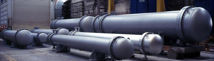
Shell and tube heat exchangers are the most widely used type of heat exchangers. The picture below shows shell and tube heat exchangers in a wide range of sizes.
General Information
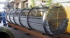
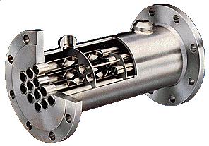
The inside of the exchanger contains many tubes and baffles, as shown in the picture below. These tubes and baffles help direct the two streams flowing through the exchange
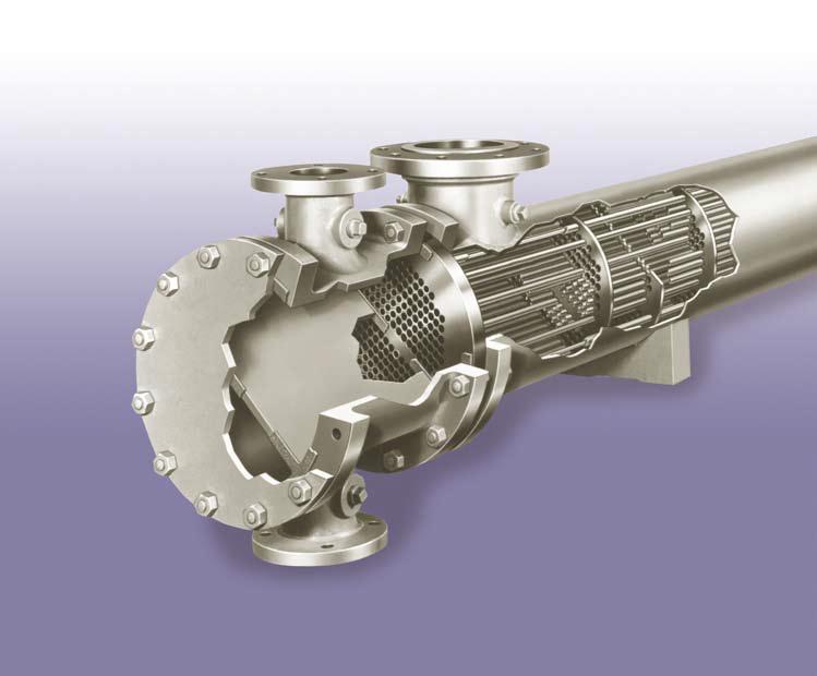
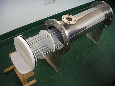
Shown below is a miniature shell and tube heat exchanger. It is used in laboratory and pilot-scale plants. These small-scale heat exchangers can handle liquid flow rates up to 20 gpm at temperatures of 1000°F and pressure up to 1500 psig.

Equipment Design
A shell and tube heat exchanger consists of several tubes enclosed in a shell. One fluid flows through the tubes while the other fluid is conducted through the shell. Flow through the shell and tubes can be countercurrent, cocurrent, or crossflow. In countercurrent flow, the shell fluid flows in the opposite direction of the tube fluid. In cocurrent flow, the shell fluid flows in the same direction as the tube fluid. Lastly, in cross-flow the shell fluid flows perpendicular to the flow of the tube fluid. In general, countercurrent flow results in the most efficient heat transfer.
The fluid passing inside the tubes has either a higher temperature or pressure, or is more corrosive than the fluid conducted throughout the shell.
The shell fluid is the fluid that flows around the tubes and baffles. The shell fluid has a lower mass and more turbulent flow than the fluid passing through the tubes.
The baffles serve two functions: Their strategic positioning supports the tubes, preventing vibration and sagging, and they also channel the fluid in the shell side, resulting in more efficient heat transfer.
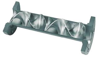
Static mixers are sometimes placed in the tubes of the shell and tube exchangers to help dissipate heat. Mixing the fluids in the tube removes temperature, velocity, and material composition gradients. Static mixers also allow fluids to be cooled near their freezing temperature without plugging the tubes.
The diagram below shows the mixing that occurs as the flow in the tube encounters the static mixer. The mixer itself does not move. For more information on mixers see the Mixers section of the encyclopedia.
Usage Examples
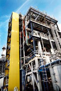
Shell and tube heat exchangers are used in a variety of industries. Some examples include heating and cooling of water, oil, and gas. Heat exchangers are also used extensively in product manufacturing. The picture below shows a heat exchanger used in a chemical manufacturing plant.
Shell and tube heat exchangers can be custom-designed for specific operating conditions.
The static mixer shown below is designed for hard-to-handle fluids and is found in many industries such as the polymer, plastic, and food industries.
More information on the role of mixing in enhancing heat exchange is available in the Equipment Design section.
Shown below is a single-pass countercurrent flow exchanger. The tubes are made of Teflon® and the shell is made of carbon steel, which can be lined with Teflon®.
Teflon® heat exchangers are ideal for use when corrosion or product contamination is a problem, since Teflon® does not corrode. Some of the fluids processed in these heat exchangers include hydrochloric acid, sulfuric acid, bleach, and water.
Advantages
- Can handle fluids at high temperatures and pressures.
- Can handle fluids of all states.
- Easy to dismantle for cleaning or repairs.
- Design can be adapted to meet operating conditions.
Disadvantages
- One unit can only be used for one duty.
- High amounts of heat loss occur, so insulation is required.
- Larger space requirements and more expensive than plate and frame.
- Over time vibrations may damage the heat exchanger. Baffle placement may be optimized to reduce vibrations and help the heat exchanger last longer.
Shell and Plate
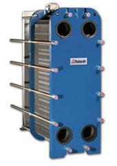
Shell and plate heat exchangers can be used for many of the same applications as shell and tube heat exchangers. A shell and plate heat exchangers are shown in the photo below.

Air Cooled
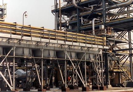
Air-cooled heat exchangers, or air coolers, use fans to move air across tube bundles. The picture below shows a typical forced draft air-cooled heat exchanger.
General Information
Air coolers are categorized as either forced draft or induced draft depending on the location of the fan. The fans for the forced draft air coolers, shown on the left, are located on the bottom of the air cooler, whereas the fans for the induced draft air coolers, on the right, are located on the top.
Equipment Design
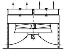
Forced draft air coolers have fans below the tube bundles, pushing the air up across the tubes, as shown in the diagram on the left. Flow in forced draft air coolers is more turbulent than in induced draft coolers, resulting in a greater heat transfer with lower costs. The low escape velocity of the heated air results in poor distribution of the recirculated air.
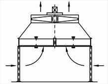
Induced draft air coolers have fans above the tube bundles, pulling air up across the tubes, as shown on the right. Induced draft coolers use less power, have more even air distribution, and have higher escape velocities, which lead to less recirculation of the heated air. However, they cost more and are noisier than forced draft air coolers.
(Copyright Allteko, Worcester, England)
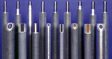
Fins may be attached to the tubes of the air-cooled heat exchanger. By increasing the contact area, fins may improve heat transfer. The pictures below show three ways of attaching fins.
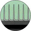
Shoulder-tension fins provide maximum heat transfer. However, they can only be used at lower temperatures.
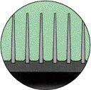
Embedded fins provide less heat transfer than shoulder-tension fins. However, they can be used at higher temperatures than shoulder-tension fins.
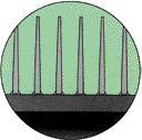
Brazed fins provide less heat transfer than either shoulder-tension fins or embedded fins. Brazing is similar to soldering, therefore brazed fins are bonded directly to the tube walls. They can withstand temperatures as high as 1100°F.
Usage Examples
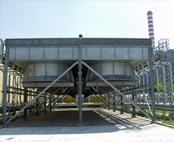
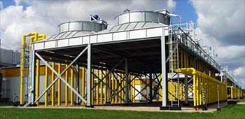
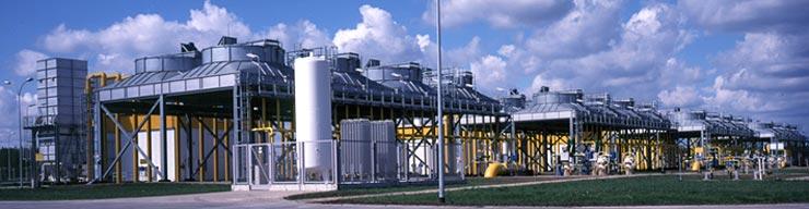
Air coolers are used for heating, air conditioning, and refrigeration in various industries such as the petrochemical, gas, chemical, and power generation industries. Air-cooled heat exchangers are generally arranged in banks, with several heat exchangers side by side, as shown below.
Advantages
- Temperature can be controlled by using shutters or by adjusting the fans.
- Eliminates the high cost of water, including the expense of water treatment.
- No pollution of water resources.
- Location does not depend on water supply.
Disadvantages
- Large space requirements.
- Possible recirculation of heated air.
- Noisy.
- Need to be careful of freezing in the winter.
Plate & Frame
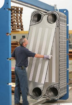
Typically, plate and frame heat exchangers are used for liquid-liquid exchange at low to medium pressures. However, gasket-free plate and frame heat exchangers can safely operate at high temperatures and pressures. Plate and frame heat exchangers offer flexibility because plates can be either added or compressed for each different situation.
General Information
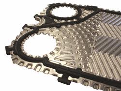
The gaps between the plates in the plate and frame heat exchangers can be adjusted according to the degree of fouling (deposits, corrosion, etc.) that is expected.
The counter-current flow of fluids that occurs in plate and frame heat exchangers allows approach temperatures as low as 1 to 2°F.
Equipment Design
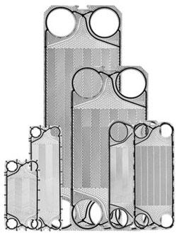
Plate and frame heat exchangers are made of corrugated plates on a frame. This design creates high turbulence and high wall shear stress, both of which lead to a high heat transfer coefficient and a high fouling resistance.
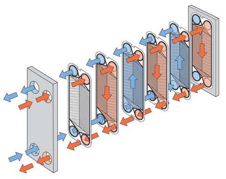
The movie below shows how the fluids travel within the heat exchanger. The two streams flow counter currently. The hot fluid flows down one plate while the cold fluid flows up the neighboring plate.
Gaskets ensure that the cold fluid (blue) and the hot fluid (red) don’t mix. Alternatives to the traditional gasket seal include brazing and laser-welding.
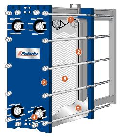
The plates are stacked in an alternating manner to cause the countercurrent flow. The diagram below shows the flow in a heat exchanger. Multiple plates are clamped together and sealed at the edges. The design allows for the two media to flow in alternate directions and not be mixed. However, heat can be transferred from one medium to the other through the plates.
The pictures shown below are examples of double-wall heat exchangers.
(Copyright Polaris Plate Heat Exchangers, Tinton Falls, NJ)
Usage Examples
Because gasketed plate and frame exchangers are easy to clean, they are especially useful for food and pharmaceutical processing, where high degrees of sanitation is required.
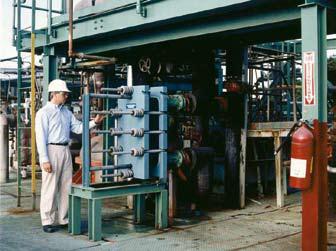
Plate and frame heat exchangers are used in the food industry for tomato sauce processing, raw milk cooling, milk pasteurization, and beer brewing. The plate and frame heat exchanger shown below is used to cool a mixture of hydrochloric acid and chlorinated hydrocarbons.
Advantages
- Require less space and are less expensive than shell and tube heat exchangers.
- Easy to adjust for different liquids by adding or subtracting plates.
- Pressure can be varied by compressing the plates.
- One frame can be used for multiple duties by simply changing plates.
- Working temperatures up to 550°C and pressures of 780 psi are possible with gasket-free versions.
- High heat transfer coefficients relative to shell and tube heat exchangers.
- Up to ten times more resistant to fouling than shell and tube heat exchangers.
Disadvantages
- Gasketed plate and frame heat exchangers have a maximum operating condition of 149°C and 300 psi.
- Not good for vaporizing fluids or large amounts of vapor.
- Gasket-free versions are impossible to open for inspection or cleaning.
Spiral
General Information
The cold fluid (blue) enters the center of the spiral and flows outwards.
The hot fluid (red) flows counter- currently, entering at the outside and flowing inwards to the center.
The spring-like coils absorb mechanical and thermal stresses minimizing the strain on tube connections, allowing it to operate at pressures above 10,000 psi and temperature gradients between two fluids of greater than 300°C.
Advantages
- Compact design requires less surface area than shell and tube heat exchangers.
- Minimal leakage.
- High cleanability.
- Can operate at high pressures.
- Works for fluids with high-temperature gradients.
Disadvantages
- Uses are typically limited to highly viscous fluids at moderate temperatures.
Falling Film
General Information
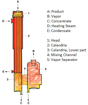
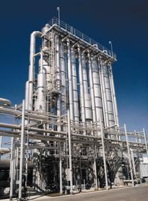
In falling film heat exchangers, the fluid enters the heat exchanger at the top of the films and the fluid flows down due to gravity. The film can be heated or cooled. The diagram on the left shows how a falling film heat exchanger is used to evaporate a liquid product. Steam is used to heat the entering liquid. On the right is an example of a falling film heat exchanger.
Advantages
- High rate of heat transfer with a short exposure time, ideal for heat-sensitive fluids.
- Easy cleanup.
Disadvantages
- Flooding.
- Restricted by pressure drop.
- Film breakup.
- Need continuous heat removal.
- Evaporation may deteriorate components.
- Liquid must be uniformly supplied.
Acknowledgements
- Alfa Laval, Richmond, VA
- Allteko, Worcester, England
- Chemineer, Inc., North Andover, MA
- GEA Process Engineering Inc., Columbia, MD
- Polaris Plate Heat Exchangers, Whitehall, PA
- PTFE-MART Inc., China
References
- Kakac, Sadik and Hongtan Liu. Heat Exchangers Selection, Rating, and Thermal Design. CRC Press, 1998. 102-103, 122-124, 249-300, 323-354.
- Kerner, Jeff. “Plate Heat Exchangers: Avoiding Common Misconceptions.” Chemical Engineering. 2 (2009):40-43. Print.
- Martin, Holger. Heat Exchangers. Washington: Hemisphere Publishing Corp., 1992: 52-82. Print.
- Perry, Robert H., and Don W. Green. Perry’s Chemical Engineers’ Handbook. 7th ed. New York: McGraw-Hill, Inc., 1998: 11-33 – 11-45, 11-47 – 11-52, 11-55. Print.
- Polley, Graham T, M. A. Vidal Farfan, and Simon J. Pugh. “Designing Shell and Tube Heat Exchangers: Avoid Vibrations From The Start.” Chemical Engineering. Jan 2012: 30-34. Print
- Saunders, E. A. D. Heat Exchangers: Selection, Design & Construction. New York: John Wiley & Sons, 1988: 3-116, 131-134. Print.
- Shelley, Suzanne. “Focus on Heat Exchangers.” Chemical Engineering. Aug (2002): 179-182. Print.
- Srinaphasawadi, Grittaya, and Wiroon Tanthapanichakoon. “Unlocking the Secrets of Plate-and-Frame Heat Exchangers.” Chemical Engineering May 2014: 52-57. Print.
- Walas, Stanley M. Chemical Process Equipment. Butterworth-Heinenmann, 1990. 189-229. Print.
- Walker, Graham. Industrial Heat Exchangers: A Basic Guide. 2nd ed. New York: Hemisphere Publishing Corp., 1990: 49-108, 264-265. Print.
Developers
- Rob Kendrick
- Mike Africa
- Joseph Palazzolo
- Andrea Roberts
- Keith Minbiole
- Eric Giuffrida