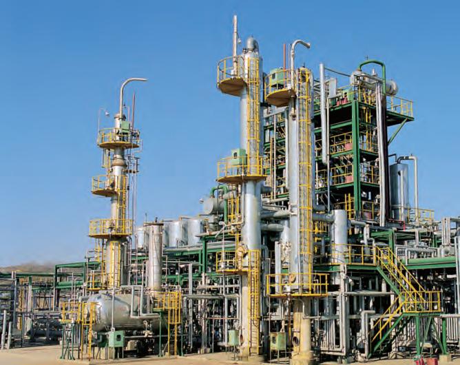
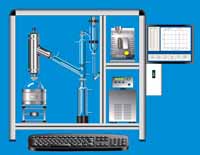
Distillation is one of the most common liquid-vapor separation processes in industry, and can be carried out in a continuous or batch system.
Distillation works by the application and removal of heat to exploit differences in relative volatility. The heat causes components with lower boiling points and higher volatility to be vaporized, leaving less volatile components as liquids. Mixtures with high relative volatilities are easier to separate. This makes separations of close-boiling and azeotropic feeds difficult, so special distillation techniques have to be used to separate these mixtures.
Distillation can be used to separate binary or multi-component mixtures. Many variables, such as column pressure, temperature, size, and diameter are determined by the properties of the feed and the desired products. Some specialized columns perform other functions, such as reactive distillation columns, which combine reaction and separation of products into a single unit.
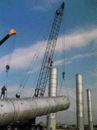
(Copyright Scanning Technologies Inc., Baton Rouge, LA)
Conventional Distillation
Packed Beds
Although packed bed columns are used most often for absorption, they are also used for the distillation of vapor-liquid mixtures. The packing provides a large surface area for vapor-liquid contact, which increases the column’s effectiveness.

(Copyright Sulzer Chemtech Ltd., Switzerland)
General Information
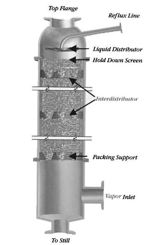
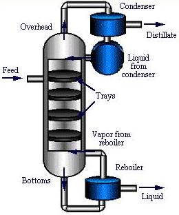
The feed mixture contains components of different volatilities, and enters the column approximately at the middle. The liquid flows downward through the packing, and the vapor flows upward through the column.
Differences in concentration cause the less-volatile components to transfer from the vapor phase to the liquid phase. The packing increases the time of contact, which increases the separation efficiency. The exiting vapor contains the most volatile components, while the liquid product stream contains the least volatile components.
(Copyright Cannon Instrument Company,
State College, PA)
Equipment Design
After the feed mixture enters the column, as the green arrows in the animation below demonstrate, liquid flows down the column through the packing countercurrently and contacts the rising vapor stream. The liquid at the bottom, which is highlighted in yellow in the animation, enters a reboiler. Two streams exit the reboiler; a vapor stream, which returns to the column, and a liquid product stream. The vapor stream flows upward through the packing, picks up the more volatile components, exits the column, and enters a condenser. After the vapor condenses, the stream enters a reflux drum, where it is split into an overhead product stream, known as the distillate, and a reflux stream that is recycled back to the column.
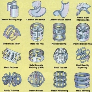
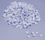
The feed passes through packing to maximize vapor-liquid surface contact for an efficient separation. Types of packing include dumped, or random, packing and stacked packing. Dumped packings have either random or geometrically structured shapes and are composed of bulk inert material, such as clay, porcelain, plastic, ceramic, metal, or graphite. Individual packings are typically 3 to 75 mm in size and have several void spaces that provide a large surface area for liquid-vapor contact. The advantages of dumped packing include high liquid flow rate capacity, high-pressure capacity, and low cost. Several examples of metal, plastic, and ceramic type packings are shown in the picture below.
(Copyright Chemical Engineering, Access Intelligence, LLC)
Metal packings have high strength and good wettability. Ceramic packings have a higher wettability than metal packings, but they are not as strong. Plastic packings have sufficient strength but experience poor wettability at low liquid flow rates. Because they are corrosion resistant, ceramic packings are used only at elevated temperatures where plastic packing would fail.
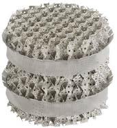
Stacked Packing is a structured meshwork of the same diameter as the column. It provides long uninterrupted channels for liquid and vapor flow. Although they are more expensive than dumped packings, stacked packings result in a lower pressure drop. Stacked packing is preferred for low liquid flow rates and in low-pressure situations. They are typically made of wood, sheet metal, or woven gauze.
(Copyright University of Michigan Chemical Eng. Dept., Ann Arbor, MI)
(Copyright Sigma-Aldrich Co. LLC, St. Louis, MO)
(Copyright Sulzer Chemtech Ltd., Switzerland)
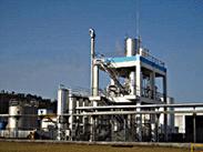
Usage Examples
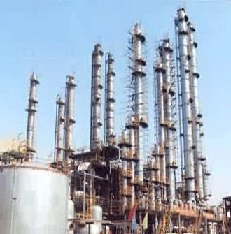
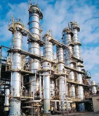
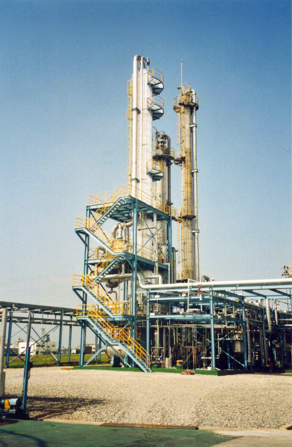
Packed bed columns are often used to recover solvents. The packed bed distillation columns pictured below to the left are used the in the petrochemical industry. The picture below to the right shows a pilot plant-packed bed column.
(Copyright Sulzer Chemtech Ltd., Switzerland)
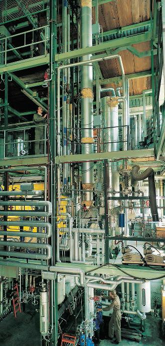
The packed columns shown below are used in an ethanolamine plant.
(Copyright Sulzer Chemtech Ltd., Switzerland)
Advantages
- Most cost-efficient distillation column when the diameter of the column is less than 0.6 m.
- Because packing can be made from inert materials, packed beds are able to handle corrosive materials.
- Lower pressure drop than in plate columns preventing column flooding.
- Good for thermally sensitive liquids.
- Suitable for low-pressure operations.
Disadvantages
- Packing can break during installation, or due to thermal expansion.
- Not cost-efficient for high liquid flow rates.
- Contact efficiencies are decreased when the liquid flow rate is too low.
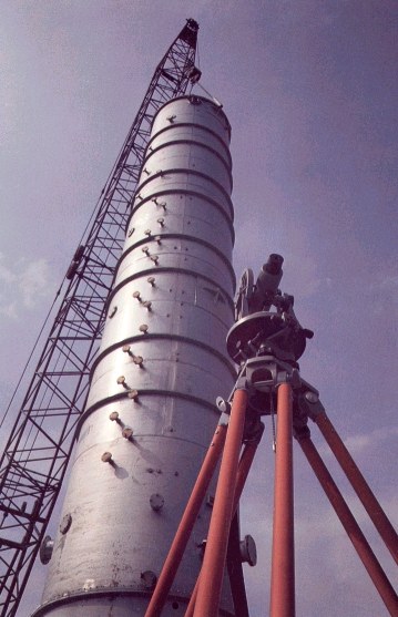
Plate
The plate, or tray column is the most widely used type of distillation column. The number of trays or stages in the column is dependent on the desired purity and difficulty of separation. The number of stages also determines the height of the column.
Works, Inc., Louisville, KY)
General Information
The feed enters a plate column towards the middle of the column. Concentration differences cause the less volatile components to transfer from the vapor stream to the liquid stream. The vapor exiting the condenser contains the most volatile components, while the least volatile components exit through the reboiler in the liquid stream.
Equipment Design
After the feed mixture enters the column, which is demonstrated by the green arrows in the animation below, liquid flows down the column and across the trays in either crossflow or countercurrent flow. A reboiler at the bottom separates the stream into a vapor stream that returns to the column and a liquid product stream; both streams are exemplified by the yellow arrows. The vapor stream flows upward through the trays, and contacts the down-flowing liquid stream, allowing the separation to take place. At the top of the column, the vapor is condensed in a condenser. The condensed stream which is shown in blue is split into an overhead product stream, known as the distillate, and a reflux stream that returns to the top of the column.
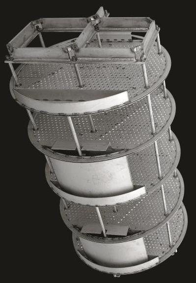
The geometry of the trays within the column affects the extent and type of contact between the vapor and liquid streams. Tray types include sieve, valve, and bubble cap. Sieve trays, which contain holes for vapor to flow through, are used for high capacity situations providing high efficiency at a low cost. Although less expensive, valve trays, containing holes with opening and closing valves, have the tendency to experience fouling due to accumulation of material. Bubble cap trays contain caps that allow vapor to flow into and out through tiny openings in the liquid. Bubble cap trays are the most advanced and expensive of the three trays and are highly effective in some low liquid flow rate situations. Bubble cap trays use the “tea cup” style in the industry today. Turndown, a term for the decrease of efficiency due to low tray vapor velocity, is important to consider when using heat integrated distillation columns
Downcomers channel the liquid flowing from one tray down to the tray below. They are shown on the edges of the trays in the picture below to the left, and their effect is demonstrated in the picture below to the right.
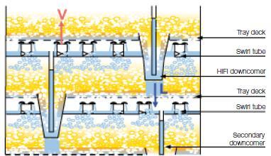
(Copyright Sulzer Chemtech Ltd., Switzerland)
Usage Examples
Plate columns are often used to recover solvents from process wastes. In the system to the left, water is used to recover methanol from a drying operation. Water comes out as the liquid product and the volatile organic waste goes into the vapor phase. Shown on the right is a 40 tray column used for mineral oils. Plate columns can also be used to purify solvents of hazardous material, such as the stripping of hydrogen sulfide from “sour water.” Many different inlet temperatures and feed moisture contents can be used.

(Copyright Odfjell, Norway)
Advantages
- Most cost-efficient distillation column for diameters greater than 0.6 m.
- The liquid/vapor contact in the cross-flow of plate columns is more effective than the countercurrent-flow in packed columns.
- Cooling coils can easily be added to the plate column (cryogenic applications).
- Can handle high liquid flow rates cost-effectively.
Disadvantages
- Higher pressure drops than packed columns which could cause column flooding.
- Foaming can occur due to the agitation of the liquid by the vapor flowing up through it.
Advanced Distillation Techniques
Vacuum
To vaporize a liquid, its temperature can be raised or its pressure can be decreased. During vacuum distillation, the pressure inside the distillation column is maintained at a vacuum to lower the temperature needed to vaporize the liquid. This method of distillation is applied in situations with heat-sensitive products, liquids with low viscosities, and liquids that tend to foul or foam.
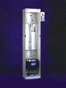
(Copyright B/R Instrument Corp., Easton, MD)
General Information
In vacuum distillation, vacuum pumps are added to the distillation system to decrease the column pressure below atmospheric pressure. In addition, vacuum regulators such as the one shown below are used to ensure that the pressure within the column is maintained in a vacuum. Careful pressure control is important because the separation is dependent on the differences in relative volatility at a given temperature and pressure. Changes in relative volatilities could adversely affect the separation.
(Copyright B/R Instrument Corp., Easton, MD)
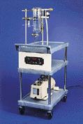
Equipment Design
The vacuum distillation unit shown below consists of a distillation column, condensing distillate, and reboiler. Vacuum pumps and vacuum regulators are added to distillation columns to maintain the column at a vacuum. Many species can be distilled at much more economical temperatures with the use of these vacuum distillation columns.
(Copyright B/R Instrument Corp., Easton, MD)
Usage Examples
Oil refineries often make use of vacuum distillation. Normal distillation techniques separate lighter hydrocarbons and impurities from the heavier hydrocarbons. This bottoms product is further distilled under vacuum distillation. This allows high boiling point hydrocarbons, such as lubricants and waxes, to be separated at economical temperatures. Vacuum distillation is also used in the separation of sensitive organic chemicals and recovery of organic solvents.
Advantages
- Columns can be operated at lower temperatures.
- More economical to separate high boiling point components under vacuum distillation.
- Avoid degradation of properties of some species at high temperatures.
Disadvantages
- High energy costs of vacuum pumps.
- Pressure and energy losses due to any leaks or cracks.
- Large column diameters are needed for the process to be efficient.
Cryogenic
In cryogenic distillation, common distillation techniques are applied to gases that have been cryogenically cooled into liquids. The system must operate at temperatures below -150°C.
General Information
During cryogenic distillation, heat exchangers and cooling coils lower the temperature inside the distillation column. The resulting system is called a cold box. Cryogenic gases are fed into a cold box and distilled at very low temperatures. The cryogenic distillation column can be either a packed bed or a plate design; the plate design is usually preferred since packing material is less efficient at lower temperatures.
Equipment Design
In a typical cold box, a nitrogen rejector cryogenically distills out nitrogen from a feed gas using two trays or packed distillation columns. The nitrogen can be bled off into the atmosphere or stored in cryogenic storage tanks. Heat exchangers keep the gases at low enough temperatures to be separated. The system’s pipes often need specially designed cryogenic valves and cryogenic fittings.
Usage Examples
Air separation is one of the main uses of cryogenic distillation. Facilities will contain a cold box as well as storage tanks for the distilled products. Outside air is pumped in and is liquefied cryogenically. This liquid air is then sent to the cold box, where it is separated into its components.
Advantages
- Most cost-efficient process for the production of large volumes of high-purity oxygen.
- Can produce both gaseous and liquid products.
- Liquid forms of cryogenic gases are easier and cheaper to transport.
Disadvantages
- Packing is not as effective at low temperatures.
- High energy costs to cryogenically cool gases.
- Special cryogenic equipment, such as valves and pumps, is required.
Reactive
Reactive distillation, or catalytic distillation, combines reaction and distillation into a single column.
General Information
A reactive distillation column can replace a separate reactor and distillation column system. Reactive distillation columns have a reactive zone lined with catalyst bales, as shown in the schematic. These bales contain beads of catalyst resin to provide as much surface area as possible for the reactants.
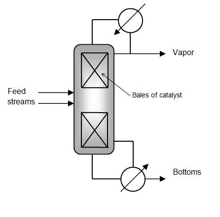
The two feed streams react in this zone. The liquid then leaves the bottom of the reactive zone as the vapor leaves the top. Depending on the reaction, the desired product may end up in the vapor stream or in the bottoms. Unreacted feed can be recycled back to the reactive zone within the distillation column.
Equipment Design
This animation shows a typical reactive distillation column. The reactants, exemplified as the incoming blue and yellow streams, enter the reactive zone. The reaction takes place and the desired product is produced, shown as the outgoing red stream. The column operation dictates the separation of reactants and products. The reactants are more volatile than the products in this example, and therefore rise upward to the distillate stream, which is demonstrated by the movement of the green arrows. The condensed reactants, also exemplified by blue and yellow, are fed back to the reactive zone. The products are less volatile, which fall down and exit the bottom stream as a liquid.
Usage Examples
Many refineries produce methyl-tert butyl ether (MTBE). MTBE can be produced in a reactive distillation column from ethanol and isobutylene. The unreacted materials are carried overhead as the distillate stream, while the less volatile MTBE product is removed as the bottoms.
Advantages
- Suppression of side reactions or by-product formation.
- Higher product selectivity.
- If reaction is exothermic, heat expelled can be used for reboiler.
Disadvantages
- Packings/catalysts for reaction can be expensive.
- Temperature needed for highest reaction rate isn’t usually the temperature needed for distillation.
- Possible high-pressure drop across reactive zone.
- Complex design due to integration of reaction and distillation.
Extractive
General Information/Equipment Design
Extractive distillation involves an additional species that acts as a solvent to change the relative volatility of one of the components of a mixture. The animation below shows the typical two-column design. The first column is known as the extractive unit. In addition to a feed stream with two components, which is shown below in green, a solvent stream also enters the extractive unit, which is exemplified below in red. The component of the feed stream that is ultimately recovered becomes associated with the solvent and leaves in the bottoms stream of the extractive unit, as the purple stream demonstrates. The other component vaporizes and exits in the distillate, as the yellow stream exemplifies. In the second column, known as the solvent stripper, the desired product, shown in blue, is separated and the regenerated solvent, shown in red, is returned to the extractive unit to repeat the cycle.
Usage Examples
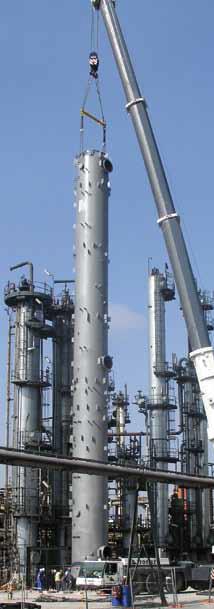
Extractive distillation is used mostly for the separation of mixtures of close-boiling species or those that form azeotropes. Extractive distillation is not as widely used in industry as conventional distillation because column simulation and design are difficult. For example, extractive distillation units are used in pulp-making processes. In the extractive unit, an organic solvent separates cellulose from lignin. The solvent is then separated, purified, and recycled in the second column. The extractive distillation unit being installed in the picture below can be used for solvent recovery, extraction of aromatic compounds, and purification of organic acids.
Switzerland)
Advantages
- Can be used for mixtures with close-boiling components that cannot be distilled using simple distillation techniques.
Disadvantages
- Large quantities of solvent are needed compared to the feed.
- High energy costs for reboiling and condensing with all the excess solvent.
Pressure Swing
General Information/Equipment Design
Pressure swing distillation is a multi-column process that exploits the effect of pressure on the composition of many azeotropes. The animation below shows one example of a variety of possible designs for pressure swing distillation systems. The feed stream and a recycle stream from the second column are fed into the first column. The first column operates at a specific pressure that separates the first component, shown in blue, as a distillate from an azeotropic mixture bottoms stream, shown in green. The azeotropic bottoms stream is fed into a second column that operates at a different pressure. At this pressure the original azeotrope is “broken” and separation can take place, resulting in the second component, shown in yellow, as a distillate and an azeotropic bottoms stream of different composition, shown in aqua. This bottoms product is recycled back to the first column.
Usage Examples
Pressure swing distillation can be used to break an ethanol-water mixture that forms an azeotrope. The columns pictured below to the left are used to distill 190 proof ethanol to 199 proof, so it can be used as a fuel grade additive, enhancing octane levels in gasoline. The process consists of three or more columns operating at different pressures. Pressure swing distillation is used in the plant pictured below to the right to recover hydrogen from a methane or methanol feed.
(Copyright Vendome Copper & Brass Works, Louisville, KY)
(Copyright Air Science, Inc., Montreal, Quebec)
Advantages
- Can separate azeotropes that are impossible to separate under simple distillation.
- Some azeotropes disappear at different pressures, making them easier to separate.
Disadvantages
- High energy and capital costs.
- Large columns are sometimes necessary.
- Large recycle flow rates.
Homogeneous Azeotropic
General Information/Equipment Design
A homogeneous azeotropic distillation system is used to separate an azeotropic feed. This animation shows how a typical system works. An entrainer, exemplified by the pink component in the recycle stream, is added to the binary feed azeotrope, shown entering the first column in green. The entrainer forms another azeotrope with one of the feed components and moves into the second column, as the purple stream exiting the top of the first column demonstrates. The other feed component separates from the azeotrope in the first column and exits through the bottom of the column, as the yellow stream demonstrates.
In the second column, the pressure is set to break the entrainer-feed azeotrope, which results in the second component, shown in blue, and a third azeotrope containing the entrainer, as the pink recycle stream demonstrates. Homogeneous azeotropic distillation is not commonly used because it is so complex.
Advantages
- Can separate azeotropic and close-boiling systems that cannot be separated with simple distillation.
Disadvantages
- Simulation and design of columns is very difficult.
- Creates two azeotropes to separate an azeotrope
Heterogeneous Azeotropic
General Information/Equipment Design
Heterogeneous azeotropic distillation incorporates liquid-liquid separation into the separation of an azeotropic feed, as shown in the animation. An azeotropic feed stream enters the first column and is split into two streams: The bottoms contain the first component, as the blue stream demonstrates, and a second azeotrope exits through the top of the column as the distillate. The distillate is condensed and sent to a decanter, where it is separated into two liquids: One is rich in component one and is returned to the first column, as the blue recycle stream exemplifies. The second liquid, which is rich in component two, is sent to a second column. The second column operates at a different pressure than the first column and is used to separate the stream into pure component two, indicated by the yellow bottoms stream, and a third azeotrope distillate. This distillate is also condensed and sent to the decanter. In addition, an entrainer is often added to improve the separation.
Usage Examples
Heterogeneous azeotropic distillation is used in chemical processing industries to separate close-boiling or azeotropic systems. This type of distillation can be used as an alternative to extractive distillation, pressure swing distillation, or homogeneous azeotropic distillation. These columns can be used to separate water-ethanol mixtures.
Advantages
- Can separate azeotropic and close-boiling systems that can’t be separated with simple distillation.
- Self-entraining systems are possible.
Disadvantages
- Simulation and design of columns is difficult.
- Large recycle rates.
Acknowledgements
- Air Science, Inc., Montréal, Québec
- B/R Instrument Corp., Easton, MD
- Cannon Instrument Company, State College, PA
- Chemical Engineering, Access Intelligence, LLC
- Odfjell, Norway
- Quincy Compressor, Quincy, IL
- Scanning Technologies Inc., Baton Rouge, LA
- Sigma-Aldrich Co. LLC, St. Louis, MO
- Sulzer Chemtech Ltd., Switzerland
- University of Michigan Chemical Eng. Dept., Ann Arbor, MI
- Vendome Copper and Brass Works, Inc., Louisville, KY
References
- Bravo, Jose L. and James K. Fair. “Distillation Columns.” Chemical Engineering Progress January 1990: 19-29.
- Cornelissen, R. L. “Energy analysis of cryogenic air separation.” Energy Conversion and Management November-December 1998: 1821-1826.
- Darton, R. C. “Distillation and Absorption Technology: Current Market and New Developments.” Chemical Engineering Research and Design September 1992: 435-438.
- Eckles, Andrew J. “Difficult to process? Vacuum it!” Chemical Engineering September 1997: 94-100.
- Fair, James R. “Design Aspects for Reactive Distillation.” Chemical Engineering October 1998: 158-162.
- Geankoplis, Christie J. Transport Processes and Unit Operations. Englewood Cliffs, N.J.: Prentice-Hall, 1993.
- Humphrey, Jimmy L. “Separation Processes: Playing a Critical Role.” Chemical Engineering Process October 1995.
- Jenkins, John, and Ken Porter. “Distillation Now.” The Chemical Engineer November 1985: 26-30.
- Jensen, B.A. “Improve control of cryogenic gas plants.” Hydrocarbon Processing May 1991: 109-111.
- Kirk-Othmer Concise Encyclopedia of Chemical Technology 4th ed. New York: John Wiley & Sons, Inc., 1999: 631-636.
- Kister, Henry Z., Rhoad, Rusty, & Hoyt, Kimberly A. “Improve vacuum tower performance.” Chemical Engineering Progress September 1996: 36-44.
- Kunesh, John G. et al. “Distillation: still towering over other options.” Chemical Engineering Progress October 1995: 43-52.
- Laikins, Robert P., “Two-Phase Concurrent Flow in Packed Beds.” Diss. U of Michigan. 1959.
- Lee, C. “Entrainment and loading rate in vacuum plate columns.” Theoretical Foundations of Chemical Engineering January 1990: 202-209.
- Lockett, M. J. Distillation Tray Fundamentals. New York: Cambridge University Press, 1986.
- Meyers, Robert A, ed. 2nd ed. Encyclopedia of Physical Science and Technology. Vol 4. Orlando, Fl: Academic Press, 1987.
- Perry, Robert H. and Don W, Green. Perry’s Chemical Engineers’ Handbook. 7th ed. New York: McGraw-Hill, 1997: 13-1 – 13-108.
- Ponting, Jeremy, Henry Z. Kister, and Richard B. Nielson. “Troubleshooting and Solving a Sour-Water Stripper Problem.” Chemical Engineering November 2013: 28-32.
- Rock, Kerry, Gildert, Gary R., McGuirk, Tim “Catalytic Distillation Extends its Reach.” Chemical Engineering July 1997: 78-84.
- Shelley, Suzanne. “Winds of change. Out of thin air.” Chemical Engineering June 1991: 36-42.
- Summers, D. (2018, February). Bubble Cap Tray Vapor Turndown. Chemical Engineering Essentials for the CPI Professional, 38-41.
- Torzewski, Kate.”Facts at your Fingerprints: Random Tower Packing” Chemical Engineering April 2008: 33.
- Walas, Stanley M. Chemical Process Equipment. Butterworth-Heinenmann, 1990. 371-458.
- Wilson, Ian D., E. R. Adlard, Michael Cooke, and C. F. Poole. “Distillation.” Encyclopedia of Separation Science. Vol. 3. San Diego: Academic, 2000. 990-1168.
Developers
- Sujata Naik
- Betsy Schornak
- Chris Seadeek
- Steve Wesorick
- Matthew Robertson
- Abigail Nalbandian
- Steve Cotton
- Nathan Hoffman
- Austin Potter