Drying is an operation in which moisture is removed thermally from a liquid/solid mixture. Dryers vary in application and function.
Rotating Drum
Rotating drum dryers, also known simply as drum dryers, dry material on the surface of a heated, rotating roll.

Nottingham, UK)
General Information
The liquid feed of a drum dryer is applied onto one or more slowly rotating steam-heated rolls. The dried product is removed by a knife-like mechanism.
Drum dryers are primarily used to dry slurries and pastes. They are available in several types; single drum, double drum, double drum vacuum, and twin drum. Selection is based on production rate, heat transfer, and system design.
Equipment Design
In single drum dryers, the feed is applied to the heated drum by applicator rolls. The number of applicator rolls used controls the application of the material, which determines the characteristics of the dried product. The dried product is removed by side blades and dropped onto a conveyor, which takes the product to the next step in the production line.
In double drum dryers, the material enters the center and is spread onto the two heated metal rolls. The material is dried and removed by the side blades as the rolls rotate. The product is dropped onto conveyor belts and is taken to the next unit in the process.
Conditions affecting a given unit’s drying capacity are feed rate, nip gap, roll diameter, and steam pressure.
Double drum dryers can also operate in a vacuum. Vacuum systems are particularly favorable when a sterile environment is required for drying or when a porous structure is desired.
Twin drum dryers are equipped with a splash feed at the bottom. As the animation below demonstrates, the feed is splashed onto the heated rolls, which rotate away from each other. The dried material is removed by side blades and dropped onto conveyors.
Usage Examples
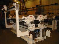
The versatility of the design allows for the use of rotating drum dryers in a wide variety of industries, ranging from food to chemicals. Special designs allow for the use of rotating drums with toxic, inert, and flammable gases by connecting the vapor outlet to a condenser. The rotating drum dryer shown below is used in the fruit and vegetable industry.
Nottingham, UK)
Advantages
- Large drying capacity
- Relatively low cost
- Large variety of feed and product moistures are possible
- Easy to operate
Disadvantages
- Big and bulky, requires a large amount of space
Rotary
Rotary dryers dry material by heated air while being transported along with the interior of a rotating cylinder.
General Information
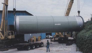
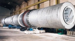
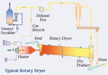
Rotary dryers consist of a rotating cylindrical shell that can be horizontal or slightly inclined. In a rotary dryer, the heat transfer mechanism can be either direct or indirect. Direct-heat rotary dryers are more common than indirect-heat rotary dryers. Shown here is a rotary dryer getting installed.
Equipment Design
Direct-heat rotary dryers dry the wet feed through direct contact with a hot gas. The gas flow can be concurrent or countercurrent to the feed stream.
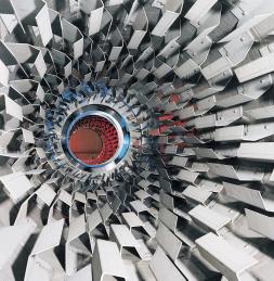
The feed dries as it is transported along with the interior of the rotating cylinder. The shell acts as both a stirrer and a conveying device. Generally, direct-heat rotary dryers are equipped with flights, like the ones pictured below, on the interior for lifting and showering the feed through the gas stream as it passes through the cylinder. In horizontal rotating cylinders, the flights move the particles down the cylinder. Choice of flight design depends on the characteristics and flow rate of the material being dried.
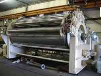
One of the most common types of indirect-heat rotary dryers is the steam-tube rotary dryer, shown below. It consists of a slowly rotating, almost horizontal shell with heat-transfer tubes along the outside walls. Steam enters the heat-transfer tubes through an inlet at the discharge end of the dryer. The feed enters at one end through a feeder and exits at the other. It is moved toward the discharge by the inclined rotation of the shell.
Usage Examples
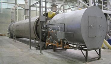
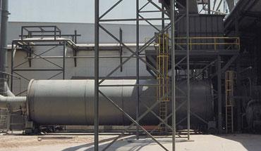
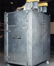
Rotary dryers are used primarily in the production of fertilizers, pharmaceuticals, and cement. Below is a picture of an installed rotary drum that could be used for food ingredients or tobacco.
Advantages
- Effects of operating parameter changes predictable
Disadvantages
- Kiln/ rolling action is difficult to quantify
- Sensitive to load and gas velocity variations
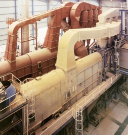
Flash
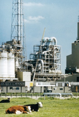
Flash drying is used to dry materials that can be transported by an air stream in large volumes. The picture below shows two flash dryers used for evaporation at 15 tons per hour.
General Information
Flash dryers process a continuous feed of wet particulate material that is dried and transported by a stream of warm or hot air. Flash dryers are similar in design to spray or fluidized bed dryers.
Columbia, MD)
Equipment Design
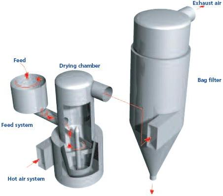
The diagram below exemplifies a general flash dryer system.
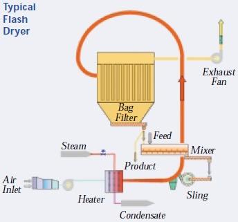
Flash dryers are grouped into two types; conventional and alternate. The main difference between the two types is that the alternate dryer includes a manifold centrifugal classifier. An example of a conventional dryer is a pneumatic-conveyor dryer, in which the hot gas lifts the material vertically while drying it. These dryers can be single or multi-stage. The schematic below shows a single-stage pneumatic-conveyor dryer.
The wet feed and hot air enter the dryer at the bottom of the conveying duct. Drying takes place in the conveyor, which has a residence time between 0.5 and 3.5 seconds. The material is then transferred to a dry product collection system consisting of a cyclone separator and filters. Dry product is removed and the used gas is vented. Some systems also incorporate a recycle stream.
Usage Examples
Flash dryers like the one shown below are used for a number of applications, such as in the production of distillers’ spent grain, sludge, corn gluten, pigments, fertilizers, and inorganic and organic chemicals.
Columbia, MD)
Flash dryers are also used to produce fine, homogeneous, non-agglomerated powders, such as the kaolin clay shown below.
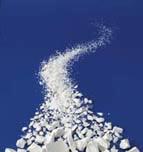
Columbia, MD)
Advantages
- Rapid heat and mass exchange, avoiding overheating of sensitive products.
- High heat transfer rates due to good contact between particles and gas.
- Circulation approaches ideal mixing, resulting in uniform product moisture concentration.
- Simple equipment with few moving parts.
Disadvantages
- Suspension and entrainment control problems.
- Particle size is limited to fine powders.
- Susceptible to overloading.
- Possible abrasion or dust formation due to high gas velocity.
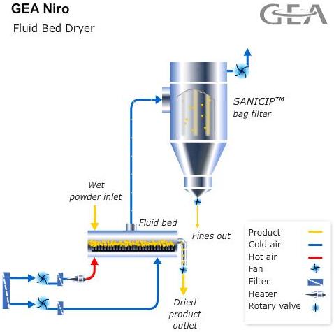
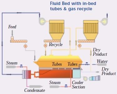
Fluidized Bed
In fluidized bed dryers, wet particulate feed is fluidized by the drying gas. A hot or warm gas passes upward through the wet particulate feed so that the material can dry while remaining fluidized.
General Information
Depending on their design, fluid-bed dryers can be run in continuous or batch modes. They can also be used to heat and cool or even to coat particles in the same unit.
Equipment Design
Fluid-bed dryers can be categorized as stationary or vibrating. Stationary fluid bed dryers can run in batch, plug flow, mixed-mode, or in stages.
In stationary fluid-bed dryers, wet material is fed at the top and dried by an upstream of hot gas, usually air. Dry product is removed at the bottom, and the air is cleaned through a cyclone and discharged at the top of the unit.
Many factors could prevent particles from becoming fluidized, such as nonuniformity or stickiness. Ideally, the material being dried should not be too dense or cause uneven air distribution.
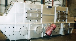
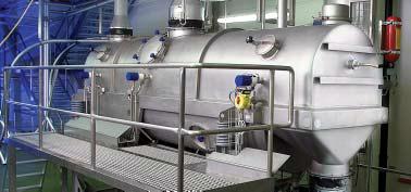
Vibrating fluid-bed dryers, such as the one shown below, are used to avoid problems caused by nonuniform or sticky particles. Materials are fluidized by the oscillation of the bed units, rather than by the flow of air.
Usage Examples
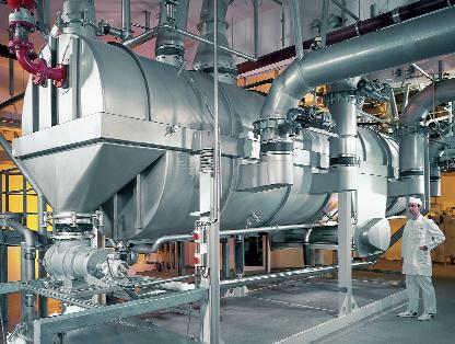
Fluidized bed dryers are used in manufacturing many products. Typical applications include the production of pharmaceutical intermediates, pigments, food products, and chemicals. The vibrating fluid-bed dryer below is used to dry several types of powders, agglomerates, and granulates.
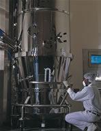
Batch mode fluidized bed dryers such as the one shown below are widely used in the pharmaceutical industry due to the small production volume requirements and vital quality assurance. They have replaced tray dryers in many industrial processes.
Advantages
- No mechanical moving parts, resulting in low maintenance.
- Rapid heat and mass exchange, avoiding overheating of sensitive products.
- High heat transfer rates.
- Even flow permits continuous, automatically controlled, large-scale operation.
Disadvantages
- Sensitive to load variations.
- Feed particle size must be equal to or less than 100 microns.
Spray
Spray dryers consist of a large vertical cylindrical chamber. Material to be dried is sprayed as droplets into a stream of hot gas.
General Information
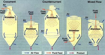
Spray dryers transform a solution, suspension, or paste into a dried product by spraying the fluid into a warm or hot drying medium that is usually air. They can operate counter currently, concurrently, or as a mixed flow process.
Equipment Design
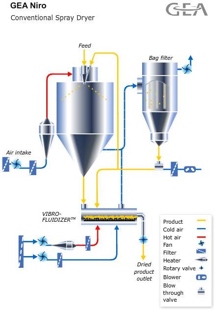
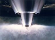
In a typical spray dryer, the cylindrical chamber has a short conical bottom. Liquid feed is pumped into a spray disk atomizer set in the roof chamber. The liquid is atomized into small drops, which are thrown radially into a stream of hot gas entering near the top of the chamber. Manipulating the temperature of this hot gas stream allows control over the porosity of the dried particles. Once drying is complete, the gas and solids are cooled and separated in a cyclone separator, where any entrained particles of solids are removed.
Concurrent, countercurrent, and mixed flow patterns are shown below.
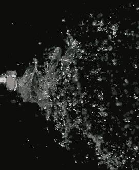
The atomizer is the most important part of any spray dryer. It determines the size, size distribution, trajectory, and speed of the droplets. The pictures below show two commonly used atomizers. On the left is a rotary atomizer and on the right is a pressure nozzle atomizer. Rotary atomizers typically spin at a rate of 5,000 to 25,000 rpm. See the Nozzles section of the encyclopedia for more information.
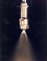
(Copyright GEA Process Engineering Inc., Columbia, MD)
The drop size determines the drying rate by regulating the available heat transfer surface and it also controls the size of the dried particle. Additionally, a larger drop size requires a larger drying chamber. Drying chambers are often found to be 20 m or taller.
Once the material has passed through, it can be collected easily from the chamber’s bottom if it is a coarse powder but fine powders have to be collected from bag filters.
Since spray drying propels large amounts of fine dust into the air, there is a risk of fire or dust explosion. However, with proper safety measures, these explosions are very rare. Spray dryers are equipped with pressure venting systems and are often operated in an inert atmosphere to help prevent ignition.
Usage Examples
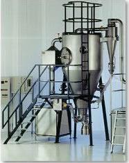
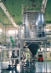
Spray dryers span a broad range of applications. They can be found in food, dairy, and plasma processes, as well as in the production of pharmaceuticals, organic and inorganic chemicals, rubber latex, ceramic powders, and detergents. The spray dryer pictured below on the left is used for dairy applications, and the one pictured on the right is used in the production of coffee.
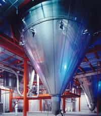
(Copyright GEA Process Engineering Inc., Columbia, MD)
Advantages
- Product properties and quality are effectively controlled
- High heat-transfer coefficients at high-temperature differences
- Easy to descale
- Relatively inexpensive
Disadvantages
- Poor heat transfer at low-temperature differences or with viscous liquids
- Requires a large amount of floor space and is heavy
- High holdup
- Highly energy-intensive, but the use of multiple drying stages can allow for the recycling of heat
- Nozzles and atomizers are easily plugged
Conveyor
Conveyor dryers are used for products that require gentle handling and large-scale production.
General Information
A conveyor dryer continuously transports material horizontally on a perforated screen through which warm air is blown.
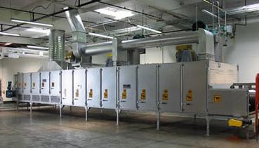
There are three types of conveyor dryers; single conveyor dryers, multi-stage conveyor dryers, and multiple conveyor dryers. Pictured below is a single-pass conveyor dryer.
Equipment Design
Wet particulate material moves through a conveyor dryer on a perforated conveyor that allows warm air to pass through. This warm air dries the material as it moves through the dryer.
The single conveyor dryer is the most widely used conveyor dryer. The dryer consists of several cells. As the conveyor moves through each cell the material is exposed to different process conditions. When the material reaches a certain point in the drying process, the airflow switches from up-flow to down-flow so that the semi-dry material is not blown off the conveyor. The last cell or set of cells is often used to cool the product.
Staging is the use of separate conveyors arranged in series so that one conveyor transfers its products to the next. This design is used when a large amount of shrinkage occurs during the drying process. As many as four conveyors can be arranged in series.
Multiple conveyor dryers are used when the product requires long, gentle drying. The material is dried as it passes from one vertically arranged conveyor to the next. The red arrows indicate the flow path of air through the dryer. In this design the dryer is not separated into cells, so the process conditions remain constant throughout the process.
Usage Examples
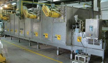
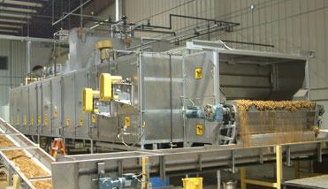
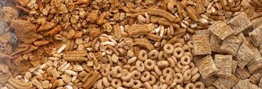
Conveyor dryers are mainly used in food production. Single conveyor dryers are used to dry snack foods, nuts, seeds, bread products, pet food, coconut, gelatin, starches, meat, and other protein products. Multi-stage conveyor dryers are used for products that may shrink while drying, such as spices, fruits, and vegetables. Below is a single conveyor dryer used for drying tobacco.
Multiple conveyor dryers are especially suited for the drying of cereals and pasta, as well as some of the other products mentioned above.
Advantages
- Can handle a variety of solids continuously and with a very gentle action
- Close control of process conditions
- Various designs available allow flexibility in process design
- Simple machine
- Easy to clean and maintain
Disadvantages
- A bed of wet material must be permeable
- Important to distribute feed carefully since there is no opportunity to rearrange it
Tray
Tray dryers are a common form of batch dryers that can use indirect or direct heat transfer.
General Information
A typical batch tray dryer consists of an enclosed, insulated housing in which trays containing solids are placed on shelves. Direct heat transfer is achieved by circulating a large volume of hot gas between the trays. Indirect heat transfer requires the use of heated shelves.
Tray dryers can be operated under a vacuum with indirect heat transfer. In this type of operation, the trays rest on hollow metal plates filled with steam or hot water. The vapors from the solid are removed by an ejector or a vacuum pump.
Equipment Design
The optimum operation of a tray dryer depends on maintaining constant temperature and uniform air velocity over the drying material. The trays are usually square or rectangular and are stacked in such a way as to allow sufficient airflow between them.
Fresh air enters through the inlet and is circulated by a fan which passes the air over heaters. The heated air is distributed uniformly over the stack of trays by baffles, drying the material on the trays. Moist air is continuously vented through the exhaust.
Usage Examples
Tray dryers are used for materials with long drying cycles, between 12 and 24 hours. They are also used when the production of several different products requires strict batch identity and thorough cleaning of equipment between batches, as in small color-pigment drying plants.
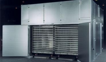
The tray dryer shown below can be used in processes involving bakery products, fruit, vegetables, birdseed, pet treats, chemicals, pharmaceuticals, and pigment.
Advantages
- Can process a variety of materials
Disadvantages
- Requires extensive manual labor
- Low output rate
- Non-uniform airflow causing overheating
- Low capacity
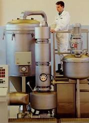
Thin-Film
Thin-film dryers are continuously agitated dryers that use minimal heat.
General Information
Unlike traditional agitated dryers, which operate at high temperatures, thin-film dryers operate at low pressures (0.01 bar or less) and low temperatures. By using less heat the dryer has a lower retention time and the walls of the dryer do not foul, which is a common problem in some dryers. They also operate using minimal utilities, have a compact design, and have a high specific evaporation capacity.
Equipment Design
There are two types of thin-film dryers: horizontal and vertical. Choosing which one to use depends on the consistency of the feedstock, the volatile component contained in the feed stream, product behavior, and desired form of the final product.
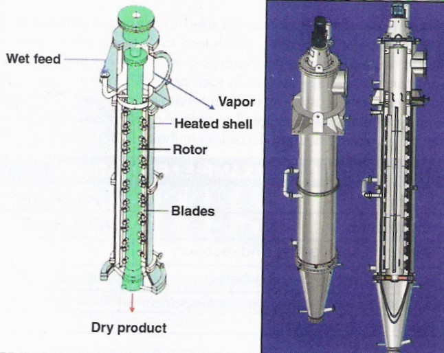
A thin-film dryer consists of a cylinder with a heating jacket that contains a close clearance rotor. The heating jacket is set at a certain temperature, predetermined by the feedstock, and is heated using electrical, steam, water, or thermal oil. The blades of the rotor spread the material evenly over the heated wall forming a thin film on the wall, as shown below.
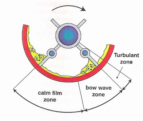
A bow wave builds up on the side of rotation of the blade, shown above, and then as the material goes through the clearance it enters the calming zone on the opposite side of the blade. As this continues the volatile component of the material evaporates, leaving a dried material.
In vertical thin-film dryers, the material begins the boil in the preheating zone. At this point evaporation and the formation of solid particles begin in the slurry zone. After some time the drying process comes to an end in the powder zone, which mostly contains the solid particles. The amount of time that the material spends in each of these zones depends on the feed rate, the volatility of the volatile component, and the operating conditions. The vapors that are produced during evaporation flow into and condense in an external condenser.
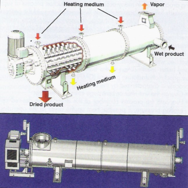
Horizontal thin-film dryers operate using blades shaped like shovels, known as mixing blades, to move the material and break up the lumps. At the same time, fixed clearance blades distribute the material evenly over the heating wall.
Usage Examples
Thin-film drying is used when the material to be dried is temperature-sensitive. Some of these materials include specialty chemicals, polymers, food products, and pharmaceuticals. This is a commonly used dryer in the pharmaceutical industry since these products require very specific processing conditions, such as low-temperature drying.
Advantages
- Low energy consumption
- Compact
- Flexibility in operation
- Only needs a single pass to dry material
- Can handle many feedstock consistencies
- Low operation temperature
- High heat-transfer rate
- Stirred tanks
- Continuous
- High turbulence in the product layer
- Completely closed design
Disadvantages
- Not suitable for coarse feedstock
- Won’t produce granular final products
Acknowledgements
- Chemical Engineering, Access Intelligence, LLC
- DeZurik, Inc., Sartell, MN
- Energy Unlimited Inc., Dodgeville, WI
- GEA Barr-Rosin Inc., St. Charles, IL
- GEA Process Engineering Inc., Columbia, MD
- Lake Innovation LLC, Lake Jackson, TX
- R. Simon (Dryers) Ltd., Nottingham, UK
References
- Chandran, A.N., S. Subba Rao, and Y.B.G. Varma. “Fluidized Bed Drying of Solids.” AIChE Journal 36 (Jan. 1990): 29-38. Print.
- Cook, Edward M., and Harman D. DuMont. Process Drying Practice. New York: McGraw Hill, Inc., 1991. 33-35, 42-54. Print.
- Hovmand, Svend, Handbook of Industrial Drying. vol. 1, 2nd ed. New York: Marcel Dekker, Inc., 1995. 195-247. Print.
- Jenkins, Scott. “Facts At Your Fingertips: Spray Drying Parameters.” Chemical Engineering. June 2012: 33 Print.
- Kelly, John, Handbook of Industrial Drying. vol. 1, 2nd ed. New York: Marcel Dekker, Inc., 1995. 161-181. Print.
- Khattab, N.M. “Optimization of the Drying Process in Batch Dryers.” Energy Sources 18 (Apr.-May 1996): 269-281. Print.
- Kisakurek, Bilgin, Handbook of Industrial Drying. vol. 1, 2nd ed. New York: Marcel Dekker, Inc., 1995. 503-523. Print.
- Masters, K. Spray Drying Handbook. New York: John Wiley & Sons, 1985. Print.
- McCabe, Warren L., Julian C. Smith, and Peter Harriott. Unit Operations of Chemical Engineering. 5th ed. New York: McGraw-Hill, 1993. 792-793, 798-801, 803-805. Print.
- Moller, Jens Thousig. A Primer on Spray Drying. Chemical Engineering. 11(2009): 34 – 40. Moore, James G., Handbook of Industrial Drying. vol. 1, 2nd ed. New York: Marcel Dekker, Inc., 1995. 249-262. Print.
- Mujumdar, Arun, Handbook of Industrial Drying. vol. 1, 2nd ed. New York: Marcel Dekker, Inc., 1995. 263-307. Print.
- Neff, Jack. “Hot Flash on Dryers.” Food Processing 59 (Apr. 1998): 74-76.
- Perry, Robert H., and Don W. Green. Perry’s Chemical Engineers’ Handbook, 7th ed. New York: McGraw Hill, 1997. 8-37, 12-39 – 12-41, 12-43 – 12-44, 12-51 – 12-56, 12-77 – 12-90. Print.
- Raouzeos, Georgios. “Thin-Film Drying Offers Deep Benefits.” Chemical Engineering. September 2012: 40-45
- Sturgeon, Lloyd F., Handbook of Industrial Drying. vol. 1, 2nd ed. New York: Marcel Dekker, Inc., 1995. 525-537. Print.
- Trystram, G., and J. Vasseur. “Modeling and Simulation of a Drum-drying Process.” International Chemical Engineering 32 (Oct. 1992): 689-705. Print.
- Van’t Land, C.M., Industrial Drying Equipment: Selection and Application. New York: Marcel Dekker, Inc., 1991. 40-143, 149-179, 212-216. Print.
Developers
- Michaiah Crump
- Melissa Schlosser
- Steve Wesorick
- Matthew Robertson
- Kelsey Kaplan
- Andrea Roberts
- Steve Cotton
- Thomas Plegue