Absorbers bring gas and liquid phases in contact, so that contaminants in the gas phase absorb into the liquid phase as a result of their interaction.
Absorption Theory
During absorption, soluble components of a gas mixture dissolve into a liquid. The animation below demonstrates that as the two streams contact, mass transfer of the soluble components takes place.
The entering gas stream, shown in yellow, contains solutes that are absorbed into the entering liquid stream, shown in purple. The exiting gas stream shown in orange leaves the column without the solute, while the exiting liquid stream, shown in blue, leaves with the solute. Absorption is usually carried out in vertical and cylindrical columns or towers. The gas and liquid phases can interact via co-current flow, counter-flow, or cross-flow.
Packed Beds
Packed bed columns use absorption to remove contaminants such as corrosive gaseous emissions, acidic fumes, and various odors. Distillation columns and packed bed columns involve essentially the same equipment.

(Copyright Tri-Mer Corporation, Owosso, MI)
General Information
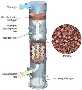
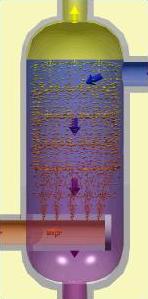
Packed beds are used to clean gas streams. As the animation below shows, gases flow up through the packed bed, shown by the arrows from orange to yellow, and the scrubbing liquid flows down the bed, shown by the arrows from blue to violet. Contaminants are transferred from the gas stream to the liquid stream. The packing provides a large surface area for the gas to liquid mass transfer to occur.
Equipment Design
A packed bed column contains a support plate, a liquid distributor, and a mist eliminator. The liquid stream flows through a liquid distributor and down the column due to gravity, resulting in counter-flow, cross-flow, or co-current flow. Contaminants are transferred from the vapor to the liquid, due to equilibrium or kinetic mechanisms, with the packing providing contact between phases for this transfer.
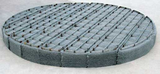
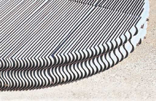
Mist eliminators are used to condense any vaporized scrubbing liquid. The picture below to the left shows a mesh mist eliminator, and the picture below to the right shows a vane mist eliminator. For more information, see the mist eliminators section of this Encyclopedia.
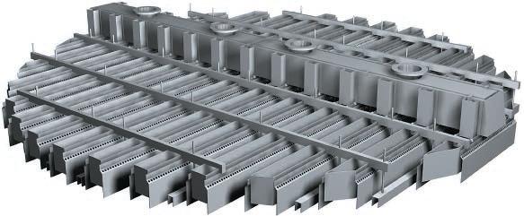
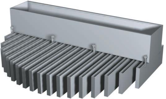
Support plates hold the packing in place within the column. The picture below shows two types of support plates.
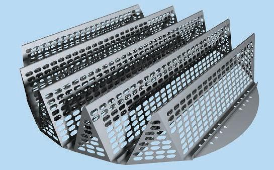
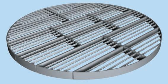
(Copyright Sulzer Chemtech Ltd., Switzerland)
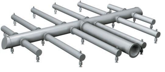
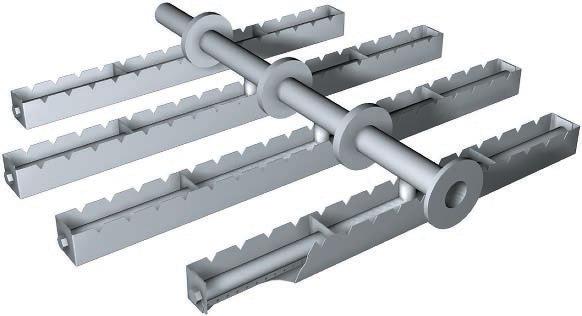
The liquid streams flow through distributors to avoid channeling, the uneven distribution of liquid, which can reduce the transfer of the gas contaminant to the liquid. A variety of distributors are shown below.
Spray-Nozzle Distributor
Extraction Distributor
Slotted Distributor
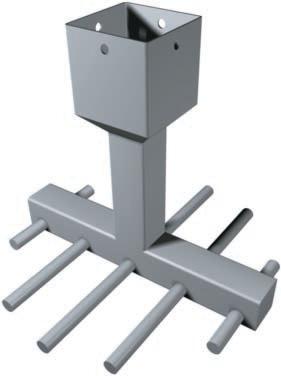
Tube Distributor
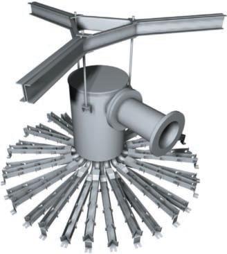
Radial Distributor
Bottom-Hole Distributor
(Copyright Sulzer Chemtech Ltd., Switzerland)
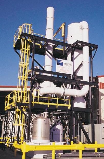
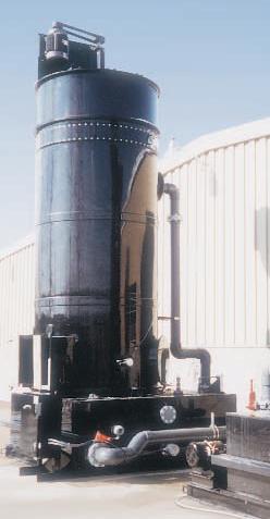
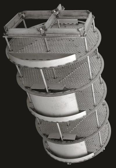
The picture below shows a packed tower. The outer shells can be made out of fiberglass-reinforced plastic, stainless steel, high-nickel alloys, non-ferrous metals, or thermoplastics. The inside packing can be made of metals, ceramics, or plastics. Inert ceramics and plastics are commonly used when operating with corrosive substances. The packing can be dumped (random) or structured.
(Copyright Tri-Mer Corporation, Owosso, MI)
Usage Examples
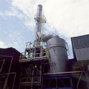
Packed beds are most commonly used in air pollution control, but they are also used in the chemical, petrochemical, food, pharmaceutical, paper, and aerospace industries. The beds shown below are used to absorb and eliminate ethylene gas from a sterilization chamber. The water-soluble ethylene gas is hydrolyzed to ethylene glycol.
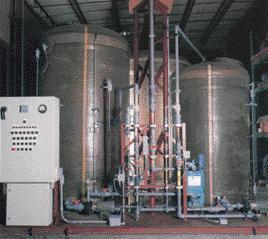
(Copyright Croll Reynolds, Inc., Parsippany, NJ)
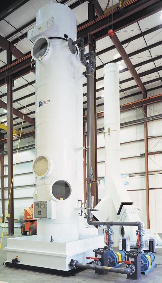
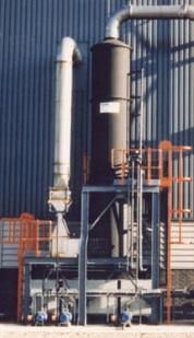
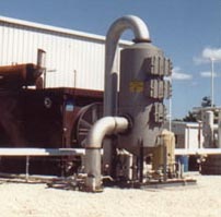
The packed bed absorption column shown below removes acidic fumes such as H2SO4, HCl, HNO3, and HF from an inlet gas stream. Packed bed absorption is commonly used when dealing with corrosive substances such as these.
(Copyright Tri-Mer Corporation, Owosso, MI)
Advantages
- Low pressure drop required.
- Small diameters possible.
- Can handle foaming systems.
- Low capital, operating, and maintenance cost.
- Simple construction.
- Can handle corrosive materials due to corrosion-resistant packing.
- Reduces back mixing in comparison to spray columns.
- Better mass transfer than in spray columns.
Disadvantages
- Fewer stages compared to other columns.
- Channeling, which must be controlled by redistributing liquid.
- Cannot handle extremely high or low flow rates.
- Cannot handle liquids with high viscosities.
- Need to be preferentially wetted to avoid reduction of the interfacial area to volume ratio.
Spray Columns
General Information
Spray columns are differential contractors, and as such, they use continuous contact between the two phases, as opposed to the stages used in staged contactors.
Equipment Design
As the animation below demonstrates, the liquid stream enters the column through spray nozzles, shown by the movement of arrows from blue to violet. Nozzles can be placed at different heights in the column. The droplets that form provide a large surface area for exposure to the gas stream; smaller droplets result in a greater exchange area. Gas flows counter-currently with respect to the liquid in the animation below, as shown by the movement of arrows from orange to yellow. The gas could also flow co-currently with the liquid. Low droplet velocities may lead to low contact or turbulence, and high droplet velocities may cause flooding. Therefore, an optimum droplet velocity is essential. A mist eliminator (not shown) is used to separate any liquid that is entrained into the gaseous phase.
Usage Examples
One example of a spray column is in the absorption of sulfur dioxide from coal-fired boiler exhaust gases.
Advantages
- Low pressure drop.
- Only one stage.
- Most effective for solutes with high liquid solubility
Disadvantages
- High pumping cost.
- Entrainment; gas carries liquid as mist.
- Poor mass transfer.
- Low residence times.
- Back mixing.
- Droplets may form improperly or coalesce.
Falling Film
General Information/Equipment Design
The animation below shows the operation of a falling film absorber. Falling film absorbers are differential contactors and are mainly used when a large amount of heat is removed during absorption. Falling film absorbers are also vertical shells and tube heat exchangers. As the animation below demonstrates, the cooling medium falls through the absorber according to the movement of arrows from teal to green. The vapor rises through the tubes, shown by the movement of bubbles from orange to yellow, and the solvent falls through the tubes, shown by the movement of arrows from blue to violet.
The solvent enters at the top and falls down the tube as a film. Gas enters at the bottom or top to produce counter-current or co-current flow. The absorption of contaminants from the gas to the solvent depends on gas velocity, liquid-gas distribution, and the tube surface condition.
Advantages
- Low-pressure drop.
- Minimal static head and residence time.
- Ideal for heat-sensitive fluids.
- Easy cleanup.
- Continuous heat removal.
Disadvantages
- Flooding.
- Restricted by pressure drop.
- Film breakup.
- Need continuous heat removal.
- Evaporation may deteriorate components.
- Liquid must be uniformly supplied.
Bubble Columns
General Information/Equipment Design
Bubble columns are a type of sparged tank. In a sparged tank, the gas stream is introduced in the form of small bubbles and acts as the agitator. As shown in the animation, gas enters at the bottom through a gas distributor or sparger, shown by the movement of arrows from orange to yellow, and is dispersed in the form of bubbles through the liquid stream, shown by the movement of arrows from blue to violet. The liquid can be introduced at the top or the bottom, resulting in either counter-flow or co-current flow, respectively. The bubbles rise at a velocity determined by the bubble size: the larger the bubbles, the faster they rise. Spargers are designed to produce consistent bubble sizes so that all the bubbles rise at the same velocity. The bubbles may contain entrained liquid, which may result in more hold up at high velocities.
Usage Examples
Bubble columns can be used to purify nitroglycerin with water; in the chemical industry for hydrogenation, oxidation, chlorination, and alkylation; and in the biotechnology field for effluent treatment, single-cell protein production, animal cell culture, and antibiotic fermentation. Bubble columns can be used for radioactive elements because there are no moving parts.
Advantages
- High thermal stability.
- Uniform distribution because of high liquid circulation.
- Low energy input requirements.
- Two gases that form an explosive mixture may be used.
- Long liquid residence time.
- Low investment cost.
- Large mass transfer area.
- Can handle radioactive materials because there are no moving parts.
Disadvantages
- Low contact efficiency.
- Back mixing.
- Short gas residence time.
- High gas pressure drop.
Tray Columns
The number of trays, or stages, in a tray column is specific to a given application.
General Information
The animation below shows a tray column absorber in action. The vapor stream flows up through the trays, as shown by the movement of arrows from orange to yellow, and contacts the down-flowing liquid stream, shown by the movement of arrows from blue to violet, which causes the absorption of the red contaminant. The equipment used is similar to that used in distillation columns.
Equipment Design
The geometry of the trays within the column affects the extent and type of contact between the vapor and liquid streams. The different tray types include sieve, valve, and bubble cap. Sieve trays contain holes for vapor to flow through. Valve trays are similar, containing holes with opening and closing valves. Bubble cap trays contain caps that allow vapor to flow through tiny openings in the liquid.
After the feed mixture enters the column, it flows down the column and across the trays in either cross-flow or counter-flow. In crossflow columns, downcomers channel the liquid flowing from one tray down to the tray below.
Usage Examples
A tray scrubber column is pictured below. Common applications include the removal of micron-sized particles and volatile organic compounds.
Advantages
- The liquid/vapor contact in the cross-flow of plate columns is more effective than the countercurrent flow in packed columns.
- Can handle high or low liquid flow rates cost-effectively.
- Can handle solids.
- Easily customized to specific requirements such as operations requiring much heat.
Disadvantages
- Higher pressure drops than packed columns.
- Slow reaction rate processes.
- Plugging and fouling may occur.
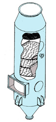
Venturi Scrubbers
Venturi scrubbers are used in the removal of gas stream contaminants by liquid droplets.
General Information
In a venturi scrubber, contact between a high-velocity gas and a free-flowing liquid causes the gas contaminants to be trapped in liquid droplets. The liquid in venturi scrubbers may contain solids, which would plug other types of absorbers. Venturi scrubbers are able to remove solid sub-micron particles.
Equipment Design
In venturi scrubbers, the gas and liquid streams enter from the top. The liquid jet enters through a nozzle to a wet approach or flooded wall entry designed to avoid buildup. Below the entry is a throat where droplets are formed by shearing. Gas contaminants are absorbed into these droplets in a single stage.
Below the venturi is a flooded elbow, or entrainment, that prevents wear. The flow is circulated in the entrainment by a pump. The gas stream and the droplets are further separated in a cyclone separator or demister. The lighter gas flows out the top, and the heavier droplets fall to the bottom, where they exit with the entrained liquid.
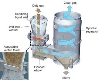
(Copyright MikroPul, Inc., Charlotte, NC)
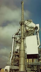
Usage Examples
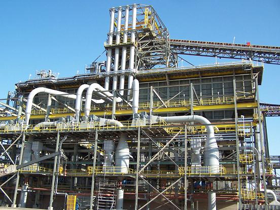
Venturi scrubbers are used to recover valuable components from hot gases, and to separate fine particles or liquid mists. The four venturi scrubbers pictured below are used in copper mining applications and operate at very high pressures.
Advantages
- Efficient atomization.
- Good contact between the gas and liquid.
- Good for the removal of submicron particulate matter as well as soluble vapor.
Disadvantages
- Pump is needed to circulate flow through the entrainment.
- Large gas pressure drop.
- Large power consumption.
- Limited to co-current flow.
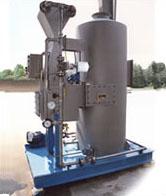
Wet Scrubbers
Wet scrubbers combine a liquid spray and cyclonic action to purify gas streams of gas compounds and dust particles.
General Information
The liquid spray in a wet scrubber removes fine particles, typically sulfur or acidic compounds, or liquid mists entrained in a gas stream. Additionally, wet scrubbers can be used to remove or reduce odors coming from a chemical or water treatment plant.
(Copyright Sly Inc., Strongsville, OH)
Equipment Design
In a wet scrubber, contaminated gas enters through an inlet at the bottom of the column. Liquid enters through a nozzle or pipe, flowing in a counter-flow, cross-flow, or co-current manner. The gas flows in a circular path within the cyclone portion of the scrubber, forcing heavier dust particles against the wall. Any liquid entrained within the remaining vapor is removed by the demister. Lighter particles hit the vane stages, where much of the vapor-liquid contact takes place. Acidic gases are converted to neutral salts and other solids so that the pH of the gas is 7 or 8. Gas exits at the top, while liquid and dust particles exit at the bottom.
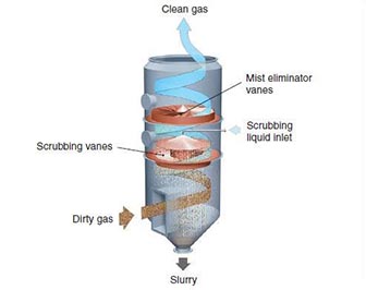
A mist eliminator, installed near the top of the spray tower, removes droplets of alkaline reactants that are transported by the flue gas stream. Mist eliminators can be made from polypropylene, fiber-reinforced plastic, polysulfone, or stainless steel. These mist eliminators can accumulate solids which can cause corrosion, fouling, and heat-related damage, so regular maintenance is critical.
Usage Examples
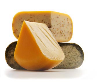
Wet scrubbers are used by the food industry, such as in cheese processing, for dust and ambient moisture removal. They also capture airborne dust in the processing of a number of cereals. In wastewater treatment plants, wet scrubbers are used to trap odorous particles into solution before releasing gaseous byproducts of wastewater treatment into the ambient air.
Advantages
- Can also recover waste heat
- Can handle flammable feeds and dust
- Can neutralize corrosive gas
- Can minimize odors from waste
- Can be used in a multi-staged configuration
- No secondary dust sources
- Relatively small space requirements
- Can handle high-temperature, high-humidity gas streams
- Low capital cost
Disadvantages
- Complex design
- High maintenance costs
- Corrosion problems with interior metal
Stirred Tank
General Information/Equipment Design
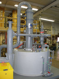
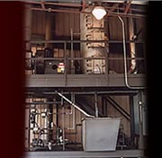
Stirred tanks, also called agitated tanks or CSTRs, are used when the absorption process includes a slow liquid-phase chemical reaction, or when close control of the process is needed. In a stirred tank, the gas is introduced directly into the liquid and mixed by the stirrer. The solids are suspended.
A cylindrical tank is typically used, with a liquid depth of one or two diameters. There are no stages in a tank. Impellers, described in the Mixers section of this Encyclopedia, are the most commonly used agitator. Propellers and turbines are also used.
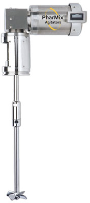
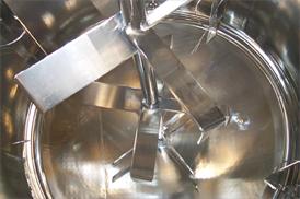
(Copyright DCI, Inc., St. Cloud, MN)
Usage Examples
Agitated tanks can be used in lime slurry carbonation, paper stock chlorination, regular oil hydrogenation, fermentation broth aeration, penicillin production, citric acid production, and aeration of activated sludge.
Advantages
- Effective for reacting systems
Disadvantages
- Some types of agitators may cause vortices
- High-pressure drop
Acknowledgements
- Advanced Air Technologies, Inc., Corunna, MI
- Amistco Separation Products Inc., Alvin, TX
- Clean Gas Systems, Inc., Hauppauge, NY
- CMI-Schneible , Holly, MI
- Croll Reynolds, Inc., Parsippany, NJ
- DCI, Inc., St. Cloud, MN
- MikroPul, Inc., Charlotte, NC
- Sly Inc. , Strongsville, OH
- Sulzer Chemtech Ltd. , Switzerland
- Tri-Mer Corporation , Owosso, MI
- Vendome Copper and Brass Works, Inc., Louisville, KY
- Wisconsin Milk Marketing Board, Inc., Madison, Wisconsin
References
- Chisholm, D. Heat Transfer Technology. New York: Elsevier Applied Science, 1988.
- Cooper, C. D. Air Pollution Control Methods. Kirk-Othmer Encyclopedia of Chemical
- Technology. New York: Wiley-Interscience, 2007.
- Darton, R. C. “Distillation and Absorption Technology: Current Market and New Developments.” Chemical Engineering Research and Design September 97: 435-438.
- Deckwer, W. D. Bubble Column Reactors. Chichester: Wiley, 1992.
- Geankoplis, Christie J. Transport Processes and Unit Operations. 3rd ed. Englewood Cliffs,
- NJ. Prentice-Hall, 1993.
- Hong, Allan, Ravindra K. Mariwala, and Michael S. Kane. “Adsorbate Shape Selectivity: Separation of the HF/134a Azeotrope over Carbogenic Molecular Sieve.” Industrial and Engineering Chemistry Research. 34 (1995): 992-996.
- Haupert, Laura. “Odor Issues and Solutions for Wastewater Treatment.” Chemical
- Engineering . September 2017: 39. Print.
- Jenkins, Scott. “Facts At Your Fingertips: Wet Scrubbers.” Chemical Engineering. December
- 2012: 27. Print.
- Kohl, Arthur L. “Absorption and Stripping.” Handbook of Separation Process Technology. Ed. Ronald W. Rousseau. New York: John Wiley & Sons, 1987: 340-344, 385-387.
- Laso, M. and von Stockar, U. “Absorption.” Kirk-Othmer Encyclopedia of Chemical Technology. New York: Wiley-Interscience, 2007.
- Meyers, Robert A, ed. Encyclopedia of Physical Science and Technology. 2nd ed. Vols. 1 and 13. Orlando, Fl: Academic Press, 1987.
- Morris, G. A., and J. Jackson. Absorption Towers: With Special Reference to the Design of Packed Towers for Absorption and Stripping. London: Butterworths Publications, 1953.
- Perry, Robert H., and Don W. Green. Perry’s Chemical Engineers’ Handbook. 7th ed. New York: McGraw-Hill Inc., 1997: 14-4 – 14-8, 14-23 – 14-30, 14-54 – 14-56, 17-32 – 17-39.
- Schifftner, Kenneth C. and Howard E. Hesketh. Wet Scrubbers. Ann Arbor, Michigan: Ann Arbor Science Publishers, 1983.
- Treybal, Robert E. 3rd ed. Mass Transfer Operations. New York: McGraw-Hill, 1980. 139-210.
- Walas, Stanley M. Chemical Process Equipment. Boston: Butterworth-Heinenmann, 1990.
- Zarzycki, Roman and Andrzej Chacuk. Absorption: Fundamentals & Applications . New York: Pergamon, 1993.
Developers
- Sujata Naik
- Steve Wesorick
- Steve Cotton
- Thomas Plegue
- Nathan Hoffman
- Emma TerBeek