Differential pressure flowmeters are a type of inferential flowmeter where the flow rate is calculated from a non-flow measurement. In this case, various methods of obstructing flow are used to create a pressure drop across a section of pipe. The flow rate is then easily calculated from the measured pressure drop using Bernoulli’s principle.
Differential pressure meters account for approximately 30% of all flowmeters due to their ease of use for continuous level measurement in constant fluid density applications. They are easily adaptable to a wide variety of applications and are good for handling high temperatures and pressures. They are, however, expensive to install relative to other types of flowmeters.
The table of content below lists a number of types of differential pressure equipment. Each section typically includes general information about the type of differential pressure equipment, equipment design, usage examples, and advantages/disadvantages.
Variable-Area
Variable-area flowmeters are among the most popular flowmeters because of their straightforward, direct reading.
General Information
In variable-area meters, fluid flowing through a slightly tapered tube causes a float (as in the animation below), piston, or vane to change position inside the tube, adjusting the area available for fluid to pass through. The fluid velocity determines the final float position.
Equipment Design
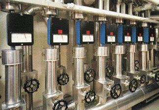
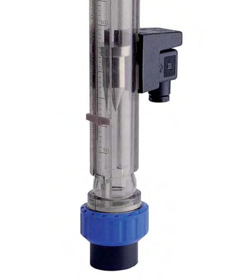
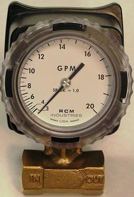
Rotameters such as the one shown below contain a float inside a tapered tube to indicate flow rate. The taper is so slight it’s very difficult to see. When a balance is reached between the upward force of the flowing stream and the float’s weight, the float is stable. The scaled or direct flow rate is read from the markings on the tube. The higher the float, the higher the flow rate. A number of tube and float shapes are used to compensate for various flow conditions.
Piston meters have a spring-loaded piston mounted on a tapered shaft in place of a float, as shown below. Fluid flow pushes the piston against the spring until the pressure forces are balanced such that the annular area between the piston and the shaft is proportional to the flow rate.
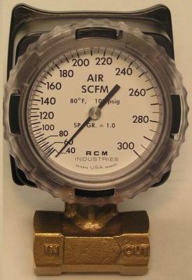
Vane meters are also spring-loaded. Fluid flow causes the vane to rotate against the spring to increase the orifice area in a chamber through which the fluid flows, as shown below.
Piston meters and vane meters can either be outfitted with electrical sensing equipment, which allows for the most accuracy, or have a pointer attached to the shaft of the spring mechanism to indicate the flow rate. In some piston meters, such as rotameters, flowrate can be read directly from tube markings.
Usage Examples
The vane meter below to the left is used for compressed air applications. The rotameter pictured on the right can be used for many applications including measuring gas flows, controlling industrial burners, monitoring compressors, and for water circuits.
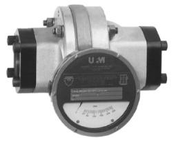
(Copyright Universal Flow Monitors, Hazel Park, MI)
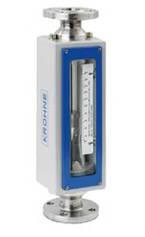
(Copyright Krohne, Inc., Peabody, MA)
Piston meters can be calibrated to handle different materials such as oil, shown below, or plain water.
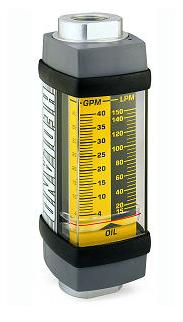
(Copyright Racine Federated Inc., Racine, WI)
Variable-area meters such as these can also be used to indicate flow of concrete additives, anesthesia delivery, suction in portable halogen leak detectors, and flow of pressurized dry air used to keep moisture out of telephone cables.
Advantages
- Low-pressure drop, which remains mostly constant across the operating range of the meter.
- Easily read, installed, and maintained.
- May be constructed from a variety of materials and cover a wide range of temperatures and pressures.
- Easily converted to handle flows of different fluids.
- Can be installed immediately before or after pipe fittings.
- Self-cleaning.
- Piston meters and vane meters can be mounted in any position.
- Low cost.
- Accurate within 2%
Disadvantages
- Requires relatively clean fluid to prevent plugging.
- Rotameters must be vertically mounted.
- Usually only provides direct readings for air and water, calculations must be made for other fluids.
- Rotameters are adversely affected by moderate to high viscosities.
- Can only be used on flows less than 200 gal/min and in pipes less than 3 inches in diameter.
- Cannot be used in systems where vibration is present.
Orifices
General Information/Equipment Design
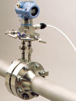
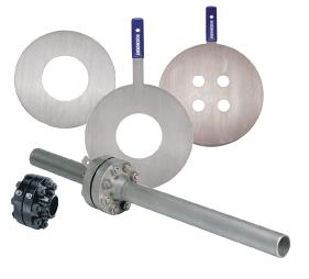
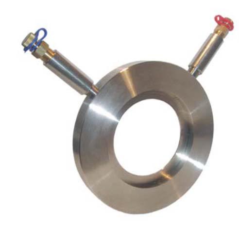
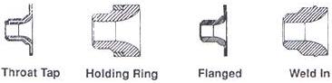
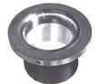
Orifices, also called orifice plates, constrict fluid flow using a flat metal disc with a circular hole in the center, as shown below. This constriction causes a pressure drop across the plate. Pressure taps on both sides of the orifice measure the differential.
The left picture below shows an orifice plate installed between flanges in a pipe. Different flow conditions are accommodated by changing the location of the orifice in the plate and the way the edge is bored, as shown below on the right.
Usage Examples
Orifice plates are the most common differential pressure meter in the chemical process industry. Most gas, water, steam, and air applications are easily metered by orifice plates.
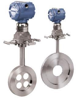
Orifices made of bronze or of steel, as shown below, can be used to meter lube oil, meter cooling water systems, and meter compressed airflow. The bronze orifice on the left meters gases while the one in the middle meters liquids.
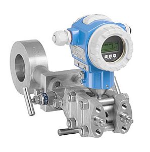
The orifice meters below are made of stainless steel and are specially designed to handle corrosive materials, such as strong acids and bases. New innovations have allowed for greater accuracy due to asymmetric sealing of the membrane. The reliability increase is created because asymmetric sealing promotes a thicker membrane, which in turn allows for a long-lasting, repeatable process.
Flow Nozzles
General Information/Equipment Design
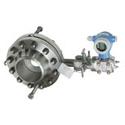
Flow nozzles are similar to orifice plates in that they contain a circular hole, smaller than and concentric with the pipe diameter, that constricts fluid flow, causing a pressure differential. In flow nozzles, however, the nozzle follows the hole, reducing the pressure differential across the device. Flow nozzles are typically used to meter steam and gases or liquids with a small degree of suspended solids.
Advantages
- Can handle suspended solids
- For same flow rate, has significantly lower pressure drop than orifice plate
- May be mounted horizontally or vertically
- Less susceptible to erosion and corrosion than an orifice plate
Disadvantages
- Unsuitable for viscous flow and sticky materials
- Requires consistently smooth flow profile, can’t handle eddies or vortices
- Requires straight pipe runs upstream and downstream
Venturi & Flow Tubes
General Information/Equipment Design
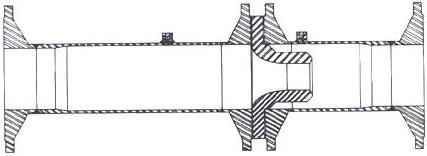
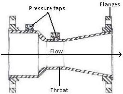
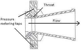
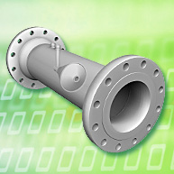
Venturi tubes are specially shaped pipe sections with tapered inlets and outlets, and straight throats. As the pipe diameter decreases, the fluid velocity increases, causing a pressure drop proportional to the flow rate across the venturi tube’s throat.
Flow tubes operate on the same principle as venturi tubes, but differ in shape. Flow tubes have no tapered entrance, but they do have a tapered throat as well as a long tapered exit. In general, flow tubes are designed to be more compact than Venturi tubes.
Usage Examples
Venturi tubes such as the one below to the left are common in water and wastewater treatment facilities, power plants, and chemical and petrochemical processing operations.
The flow tube to the right is designed to meter fluids such as cooling water, steam, and combustion air.
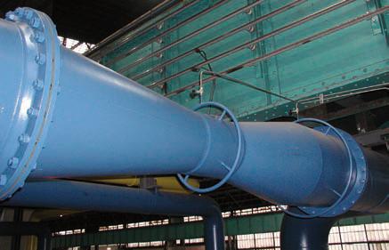
(Copyright Endress+Hauser, Inc., Greenwood, IN)
Advantages
- Handle large flow volumes at low-pressure drops.
- No moving parts, low maintenance.
- Accommodate liquids with high solids content.
- Shape is inherently self-cleaning.
- May be mounted horizontally or vertically.
Disadvantages
- Require four or more pressure taps to accurately measure pressure differential.
- Require lengths of straight pipe upstream and downstream.
- Accuracy depends on consistent flow profile.
- Less accurate at low flow rates.
Pitot Tubes
General Information/Equipment Design
Pitot tubes measure the difference between impact pressure in a flowing stream and static pressure at the pipe wall. The impact tube’s end is bent at a right angle to face the flow and has a hole in the tip, as shown in the animation. Fluid flows into the hole and up the length of the tube.
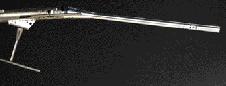
The static tube is straight and has one or several holes along its length, as shown in the pictures below. The height of the liquid in the tube indicates the pressure.
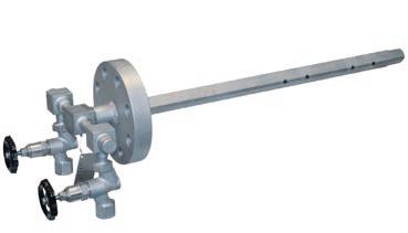
Pitot Tubes (Copyright Endress+Hauser, Inc., Greenwood, IN)
For more information about how pitot tubes work, see the Pressure Measurement section of this encyclopedia.
Usage Examples
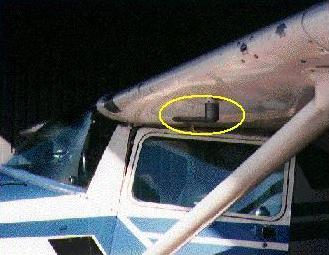
Pitot tubes are used industrially to meter clean liquids, gases, and steam. They are most frequently used to measure air velocity, particularly in HVAC systems, but in other applications as well. For example, pitot tubes can be seen in the plane to the left and NASA’s X-31 fighter jet to the right. The jet travels at speeds of 1000 mph at an altitude of 40,000 ft. Most jets can only travel at 250-500 mph.
Advantages
- Suitable for measuring steam
- Low-pressure drop
- No moving parts, low maintenance
- Easy to install and ideal for retrofitting
- Inexpensive
Disadvantages
- Subject to clogging
- Limited to point measurements
Target
General Information/Equipment Design
Target meters measure the force of a flowing stream on a target, usually, a vane or disc, suspended in the stream. The force on the target, measured by a strain gauge, is directly proportional to the stream’s velocity.
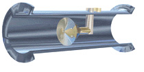
The animation (above right) shows a target flow meter being used for solid particles. The gray plate measures the force the particles exert as they flow through the meter. The magnitude of the force depends on the velocity, angle of impact, mass, and energy-absorbing tendencies of the solids. The force is proportional to the flow rate.
Usage Examples
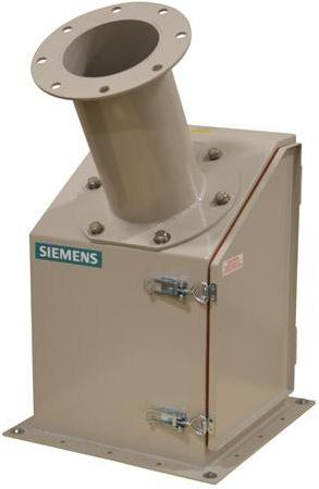
Target meters are much less common than other differential pressure flow meters, but they are among the very few flowmeters capable of measuring solids flow. The picture below shows one type of this meter that can handle solids from grains to cement.

Target meters are primarily used in water and steam applications, but can also be used on other types of wet gas. In addition to the chemical process industry, target meters are also found in the food and beverage, dairy, and pharmaceutical industries.
Advantages
- Particularly useful for steam, corrosive materials, and liquid flows with suspended solids
- One of the only methods of measuring solids flow
- Low maintenance
- Easily adaptable to different fluids and flow rates by changing the target size and material
Disadvantages
- Reduced accuracy in gas and liquid metering compared to other types of flowmeters
V-Cone
General Information/Equipment Design
V-cone flowmeters work in much the same manner as other differential pressure flowmeters. A cone inserted into the path of flow causes a pressure drop proportional to the flow rate. Pressure taps are located slightly upstream and in the downstream face of the cone. The shape of the cone is designed to smooth the velocity profile so that an accurate measurement can be made regardless of the fluid’s flow characteristics. V-cone flowmeters are often used in applications where static mixing is desired due to the formation of vortices at the base of the cone.
Usage Examples
V-cone flowmeters are often used in chemical and pharmaceutical processing, the food and beverage industry, the pulp and paper industry, and water and wastewater treatment operations.
They are also commonly used to meter air flow for fans and air motors, and leakage from airplane cabins and home windows.
Advantages
- Don’t require straight pipe runs, can be located closer to upstream disturbances than other differential pressure meters
- Lower pressure drop than orifice plates
- Low cost
- Vortex formation immediately behind the cone encourages mixing, prevents buildup
- Accuracies within 0.5% are possible
- Can handle dirty fluids, including those with suspended solids
Disadvantages
- Reduced accuracy at lower flowrates
Elbow Meters
General Information/Equipment Design
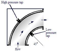
When fluid flows through an elbow, it exerts centrifugal force on the inside of the pipe wall, creating a pressure differential between the inner and outer radii of the elbow. Pressure taps in the elbow measure this differential, which is proportional to the elbow’s radius. In most cases, one tap at the 45° point is enough, as in the schematic, but an additional tap at the 22.5° point may also be used. Elbow meters are used when lack of space prohibits use of most other flowmeters, which require long, straight pipe.
Acknowledgements
- Emerson Process Management , Chanhassen, MN
- Endress+Hauser, Inc., Greenwood, IN
- Herz Valves UK, Ltd., Guildford Surrey
- Imperial Flange & Fitting Co., Inc., Los Angeles, CA
- Krohne, Inc. , Peabody, MA
- McCrometer, Inc., Hemet, CA
- NASA-Dryden, Edwards, CA
- Racine Federated Inc., Racine, WI acquired by Badger Meter
- RCM Industries, Concord, CA
- Siemens Milltronics Process Instruments Inc., Peterborough, Ontario
- TurnaSure LLC, Langhorne, PA
- Universal Flow Monitors, Inc., Hazel Park, MI
References
- Digiacomo, Ronald W., “Measuring Flow.” Chemical Engineering, 7(2011): 30 – 34.
- Omega Complete Flow and Level Measurement Handbook and Encyclopedia, Vol. 29. USA: Omega Engineering Inc., 1995: B-3 – B-6, B-10, Z-11, Z-18. Print.
- Jenkins, Scott. “Pressure Based Level Measurement.” Chemical Engineering. May 2017: 38.
- Kiker, E. (2018, February). Improvement in DP Level Measurement. Chemical Engineering Essentials for the CPI Professional, 46-49.
- McCabe, Warren L., Smith, Julian C. and Peter Harriot. Unit Operations of Chemical Engineering. New York: McGraw-Hill, 1993: 223 – 226, 229-230. Print.
- Miller, Richard W. Flow Measurement Engineering Handbook. 3rd ed. New York: McGraw-Hill, 1996: 6.5 – 6.10, 6.12 – 6.13, 6.15 – 6.16. Print.
- Perry, Robert H., and Don W. Green. Perry’s Chemical Engineers’ Handbook. 7th ed. New York: McGraw-Hill, 1997: 8-48, 10-8 – 10-9, 10-13 – 10-19. Print.
Developers
- Erica Mauter
- Joseph Palazzolo
- Steve Wesorick
- Matthew Robertson
- Kelsey Kaplan
- Andrea Roberts
- Henry Chen
- Emma TerBeek
- Austin Potter