The ability to store energy after it is generated is critical to successful energy systems to ensure that it’s available on demand. Energy sources that are not stored in mechanical energy systems take the form of alternating current (AC) electrical energy, which are later converted into direct current (DC) electrical energy for storage. Each type of storage system is composed of a storage medium, a power conversion system (PCS), and the balance of the plant (BOP).
The storage medium is an energy reservoir that can take the form of chemical, mechanical, or electrical potential energy, with the type of storage medium chosen depending on the technology’s capacity and its application. The PCS consists of the power electronics that allow the conversion between AC and DC electrical energy and vice versa. It also controls the power during conversion to prevent damage to the storage unit and electrical system. The BOP includes the facility that houses the equipment, the environmental control units, and the electrical units that connect the power grid to the storage medium through the PCS.
Pumped-Hydroelectric Storage (PHS)

General Information
This type of storage unit facility is the oldest and the most abundant in the world. Energy is stored as mechanical potential energy, where gravity is the driving force.
Equipment Design
The conventional configuration of PHS systems consists of two vast reservoirs, one located at a higher elevation than the other, between 30m to 650m above base level with a 300m difference between the two reservoirs. Water is released from the upper reservoir to the lower reservoir, passing through hydraulic turbines that generate electrical power. These facilities typically run with a daily 60% efficiency that depends primarily on their impellers and variable speed motors, with either freshwater or seawater as their working medium.
Usage Examples
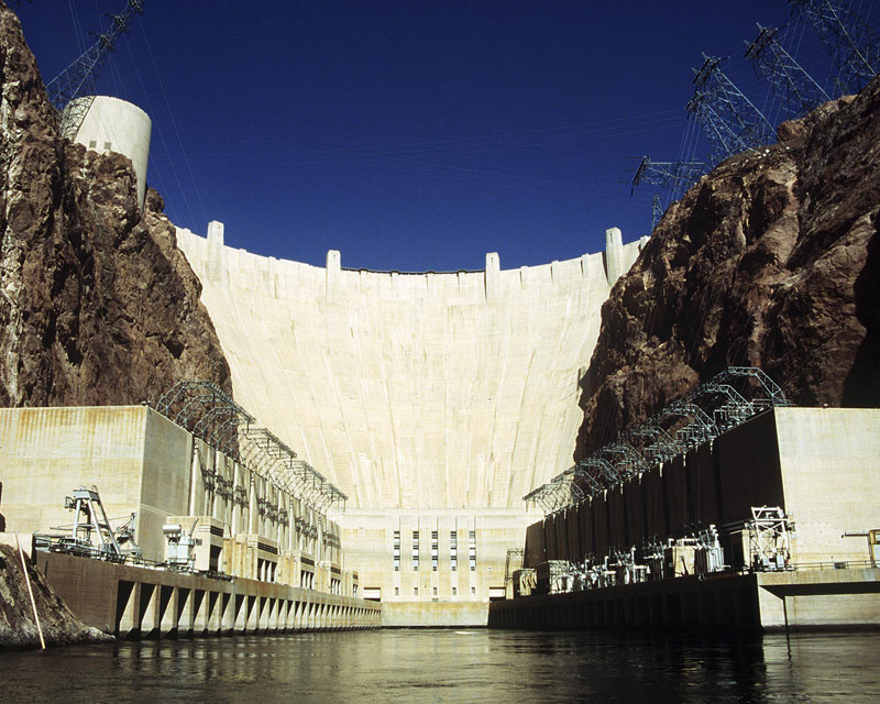
The most well-known application of hydroelectric usage and storage in the United States is the Hoover Dam. The Hoover Dam generates, on average, 4.2 terawatt-hours per year, which is enough to service 1.3 million people in California, Arizona, and Nevada. Additionally, the Hoover Dam serves as a massive “battery” that can generate more or less power, depending on need, and can even consume excess energy when there is an excess in the electrical grid, effectively mitigating the risk of blackouts due to power overload.
Compressed Air Energy Storage
General Information
Compressed air energy storage (CAES) units use excess power generated during off-peak hours to pressurize air into an underground reservoir. The air is later released during peak hours to power gas turbines to generate electricity. This technology substitutes the expensive natural gas fuel used to power a gas compressor with lower-cost energy that is available from an off-peak facility such as wind power or nuclear power facilities.
Equipment Design
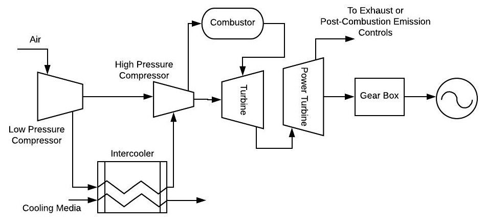
The components of CAES include a generator, air compressors, a turbine train that functions at varying pressures, controls for combustion and equipment operations, and the balance of plant auxiliary equipment systems. Power is generated when the compressed air is exhausted from the underground chamber through an expander. Efficiency of the CAES is increased by installing a recuperator, a heat exchanger that preheats the gas prior to releasing it from the underground reservoir. It allows the air to be the needed temperature and pressure to the combustor unit.
Usage Examples
CAES systems are often used to store energy captured by solar power generation or from wind power generation in an effort to regulate the amount of energy being produced in these forms of energy generation, due to the lack of completely consistent sunlight or wind. CAES systems can then hold energy from the electrical grid like a battery and supply it to the grid when there is higher electrical demand.
Flow Batteries
General Information
Flow batteries store and release energy through a reversible electrochemical reaction between two electrolytes. As illustrated in the Fuel Cells module, the types of electrolyte tank systems used will depend on the type of flow battery used, such as alkaline, phosphoric acid, or direct methanol, among others. The common types of flow batteries are zinc-bromine, redox, vanadium redox, and chromium ion. Energy storage capacity, measured in megawatt-hours (MWh), is determined by the size of the electrolyte in the flow battery, while the power, measured in megawatts (MW), is dependent on the type of cell stack in the flow battery.
Equipment Design
Flow batteries are typically made up of four subsystems: cell stacks, an electrolyte tank system, a control system, and power conversion systems (PCS). Cell stacks are composed of a cathode, and an anode that may or may not include bipolar plates. The electrolyte tank system is the liquid, and sometimes metal, which stores the energy at all times for charging and discharging. The control system is what allows an operator to determine when the flow battery is charging or discharging. The power conversion system is closely connected to the control system as this is the part of the battery which actually performs the charging and discharging of the flow battery through direct current (DC) converters.
Usage Examples
The cathode and anode of the electrolyte in the flow battery are separated by a membrane, allowing for flow batteries to last much longer than similar lithium-ion batteries such as those found in cell phones. The exchange of charged fluids in flow batteries can produce electrical discharge without degradation. Thus, flow batteries are ideal for longer-use applications and have been shown to operate for up to 20-50 years. Flow batteries are often used to store energy at utility companies and have become very popular for renewable energy electricity storage, such as solar power or wind power electricity storage.
Flywheels

General Information
Flywheels store energy by accelerating a rotor to a high speed and maintaining it as rotational kinetic energy. To maintain the energy in the system, any resistance is minimized by using magnetic bearing systems and by keeping the rotor system inside a vacuum chamber to reduce frictional losses and minimize heat transfer in and out of the unit. Flywheels have the ability to produce very high voltages and thus require transformers to handle the high voltages and may contribute to losses within the system.
Equipment Design
A flywheel’s components consist of a rotor, motor, bearing system, vacuum housing, and power conversion systems (PCS). When power is required, the flywheel releases its stored energy through usage of the motor as a generator and it eventually slows down from its initial rotating speed. This allows the flywheel to be used for deep discharges without damaging the storage unit because energy is stored mechanically instead of chemically. The most important component of a flywheel energy storage system is that it is in a vacuum to eliminate frictional losses that may be caused by the air or bearings of the system.
Usage Examples
Flywheels are often utilized within large distribution networks to regulate power distribution. To counteract voltage drops or interruption in electricity supply, flywheels may store energy during times of less use, and then supply voltage to the system when the network encounters power quality problems within the grid. Flywheels have a longer lifespan and fewer components than battery systems. This technology has the potential to improve network stability and reliability in large distribution networks.
Electrical Capacitors
General Information
Capacitors are energy storage devices that use electrostatic charges on the opposite surfaces of two plates. The amount of charge stored is referred to as the capacitance.
Equipment Design
Electrochemical Capacitors (ECs) closely resemble a battery in that they contain two electrodes typically immersed in an electrolyte separated by a porous separator. Capacitors separate the positive and negative charges from the electrolyte ions into the respective plate surface and are able to move electrical charges through solid materials, unlike batteries that require an electrochemical reaction. This allows them to be cycled many times and to not be affected by deep discharges, unlike chemical batteries.
Usage Examples
ECs function much like a battery in the sense that they can withstand many charge and discharge cycles. They do not need any servicing in their lifetime and do not require any special disposal for hazardous substances. This makes them ideal for solar cell use as solar cells can last for many years, as can ECs. Additionally, ECs can withstand high energy input during peak sunlight times during the day and then slowly discharge energy to the electrical network throughout the day and night. This couples with the fact that ECs produce no hazardous waste, making them an ideal choice for storing energy for a homeowner utilizing solar energy to reduce one’s environmental impact.
Superconducting Magnetic Energy Storage (SMES)
General Information
SMES units use the magnetic field produced from the flow of direct current in a coil of a cryogenically cooled superconducting material to store electrical energy. This storage unit is suitable for short interval discharges, as a high energy output can only be produced in a brief amount of time. Superconductivity does not rely on chemicals and no toxic byproducts are produced by the process, making them more environmentally friendly than batteries.
Equipment Design
Key components of this system include a superconducting coil, a power conditioning system, a Cryogenic Refrigerator, and a vacuum vessel to maintain the coil in a superconducting state at low temperatures. At low temperatures, superconducting coils that are typically made up of niobium-titanium RE cooled to 4.2 K by liquid helium. The low temperature environment enables the superconducting coil to carry large current with little loss of power while avoiding the loss of magnetic energy from resistance in the wire.
Usage Examples
SMES systems have been used mainly within nuclear fusion power plants as well as within high-speed railway systems. SMES systems can compensate for fluctuating energy loads by releasing and absorbing energy when needed. Due to high costs and initial investments of SMES systems it is not practical to use them on a smaller scale than power plants or transportation systems.
Thermal Energy Storage (TES)
General Information
This type of storage unit is mostly used with a building’s existing cooling unit, using either water or ethylene glycol during off-peak hours that will act as a supplementary cooling medium later during peak hours in the day. Other kinds of thermal energy storage utilize heat transfer fluid, and either maintain the heat in this fluid for storage or transfer it indirectly to another type of heat storage fluid. The high heated fluid then flows into a heat exchanger where it can be used to produce steam for electricity production.
Equipment Design
Cooling unit systems consist of a heat exchanger unit with helical plastic or metal coils stored inside an insulated chamber, a refrigerant pump, and a condensing unit. At night, the refrigerant is chilled, since cooling is not needed by the building facility. Systems utilizing heat transfer fluid also consist of a heat exchanger to create steam, which can then power a turbine to create electricity.
Usage Examples
TES units often serve as an optimizer to the cooling unit of the building. In the daytime, the chilled refrigerant is circulated throughout the building by the chiller system. TES units are also utilized to store solar thermal energy. After the energy from the sun is absorbed from the receiver, a cool heat transfer fluid may be heated by this absorbed energy, and the transfer fluid can then be used elsewhere to make steam and power a turbine for electricity.
Acknowledgments
- U.S. Department of the Interior, Bureau of Reclamation, Boulder City, Nevada.
- Prof. Andrej Lenert, Chemical Engineering, University of Michigan
References
- R. Baxter, Energy Storage: A Nontechnical Guide. Tulsa: PennWell, 2006.
- I. Penn, “The $3 Billion Plan to Turn Hoover Dam Into a Giant Battery”, Nytimes.com, 2018. [Online].
- U.S. Bureau of Reclamation, “Hoover Dam”, 2018.
- “Compressed Air Energy Storage (CAES) | Energy Storage Association”, Energystorage.org. [Online].
- R. Whitlock, “Compressed Air Energy Storage (CAES) Systems”, Interestingengineering.com, 2016. [Online].
- J. Lim, S. Lee and K. Kang, “A Modular Power Conversion System for Zinc-Bromine Flow Battery Based Energy Storage System”, in 2015 IEEE 2nd International Future Energy Electronics Conference, Taiwan, 2015.
- K. Zipp, “What is a flow battery?”, Solar Power World, 2017. [Online].
- T. Aljohani, “The Flywheel Energy Storage System: A Conceptual Study, Design, and Applications in Modern Power Systems”, International Journal of Electrical Energy, vol. 2, no. 2, 2014.
- M. Carlen and R. Kötz, “Principles and Applications of Electrochemical Capacitors”, Electrochimica Acta, vol. 45, no. 15-16, pp. 2483-2498, 2000.
- D. Sutanto and K. Cheng, “Superconducting Magnetic Energy Storage Systems for Power System Applications”, in Proceedings of 2009 IEEE International Conference on Applied Superconductivity and Electromagnetic Devices, Chengdu, China, 2009.
- U.S. Department of Energy, “Concentrating Solar Power Thermal Storage System Basics”, Office of Energy Efficiency and Renewable Energy, Washington D.C., 2013.
Developers
- Nuramani Saiyidah Binti Ramli
- Emma TerBeek