Fans are used to transport gases under low pressures (less than 0.5 psi). Fans can be separated into two major categories: centrifugal and axial flow. Air is discharged radially from centrifugal fans and axially from axial-flow fans.
Some common uses for fans in chemical processes are pneumatic conveying systems, ventilation, and air pollution control systems. In pneumatic conveying fans are used to convey air across the system. For ventilation and air pollution control they are simply used to divert pollutants, harmful fumes, or vapors away from people to keep the air clean.
Centrifugal
Steel Plate
General Information
Steel plate or “paddle wheel” fans are the simplest and oldest types of fans in use. Six to twelve large, flat steel plates serve as the fins for the fan. The fins are deep radially, with the heel and tip edges parallel to the shaft. The tip length is usually longer than the heel length.
As the animation below shows, air enters the fan axially. It is then discharged radially from the fins.
Equipment Design
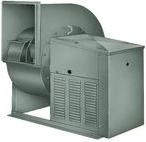
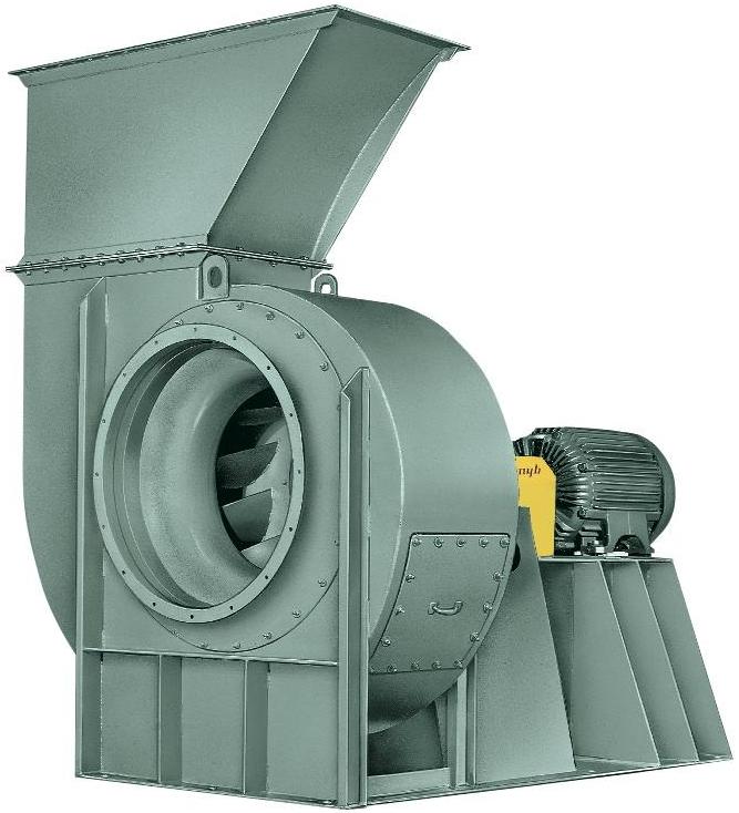
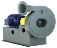
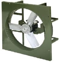
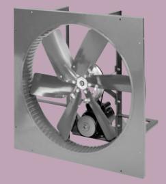
Steel plate fans are usually placed inside housings like the one below to direct the flow of air.
Steel plate fans are generally bulky for the amount of air they handle. They operate at low speeds and pressures below 0.22 psi (11.2 mm Hg). The simplicity of steel plate fans is the main reason they are still used today. Pictured below is a fan that has a radial paddle wheel.

Curved
General Information
Curved fans represent a large portion of the fans in use today. The distinguishing feature of curved fans is the curvature of their fins. They work in much the same way as other centrifugal fans.
(Copyright Lau Industries, Dayton, OH)
The fan pictured below on the left is a forward curved fan, and the fan pictured on the right is a backward curved fan.
(Copyright The New York Blower Company, Willowbrook, IL)
Equipment Design
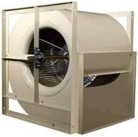
Forward-curve fans, also known as multivane, multiblade, squirrel cage, or sirocco fans, are the most common curved vane fans.
The vanes, which number from 24 to 66 per fan, are parabolic steel plates arranged so that the concave side is forward in the direction of rotation. Air enters the fan axially and is discharged radially as the movie below shows.
Forward-curve fans are volume fans, requiring a minimum of space for a given capacity. They also run at a higher speed and efficiency than steel plate fans.
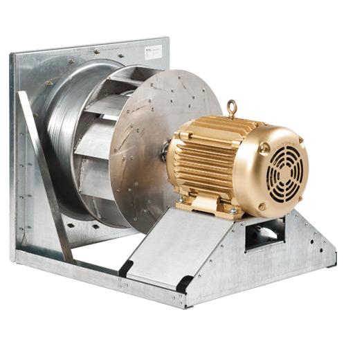
Backward-curve fans are similar to forward curve fans, except that the convex side of the fin faces the direction of rotation. Backward curve fans are also called forced draft, turbovane, silent vane, radial flow, and high speed fans.
The fins, about 16 per fan, are usually heavy and long, and oriented with the tips parallel to the shaft. Air enters the fan axially and is discharged radially.
Backward-curve fans have capacities smaller than forward-curve fans but greater than steel plate fans. They are quiet, highly efficient, and achieve the fastest tip speeds of all fans.
Reverse-curve fans are a cross between forward- and backward-curve fans. The fins resemble forward-curve fins at the heel, and backward-curve fins at the tip. The inflection point lies midway between the ends.
As the animation below shows, air enters the fan axially and is discharged from the fins radially.
Radical-Tip
General Information/Equipment Design
Radial-tip fans represent a cross between forward-curve and steel plate fans. The heel of the fin is curved to resemble the parabolic shape of forward-curve fins, while the tip side is straight, as in the fin of a steel plate fan.
Conveying
General Information
Conveying fans can handle gases with solid particles suspended in them. As the animation below shows, air and suspended particles enter the fan axially, and are then discharged radially.
Equipment Design
Conveying fans have no rivets and are run at low speeds to prevent solids from collecting on the fan and causing damage. Conveying fans can also be designed to separate solid particles.
The pictures on the left and right show two common wheel designs for conveying fans.
(Copyright The New York Blower Company, Willowbrook, IL)
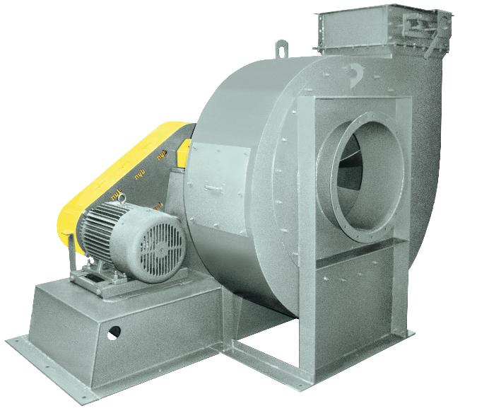
Pressure Blowers
General Information
Pressure blowers are used for high pressures (0.87 psi, 44.8 mm Hg). As the animation to the left shows, air enters the blower axially. The air is then discharged radially from the fins.
Equipment Design
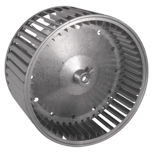
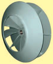
Pressure blowers are generally tall and narrow, with blades that have great radial depth; the fins have little to no curvature. The inlet diameter is small relative to the casing. Pictured on the right is a standard aluminum wheel that could be found inside a pressure blower.
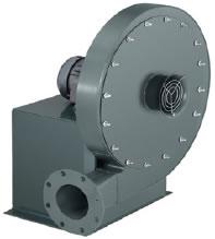
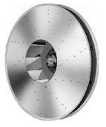
(Copyright The New York Blower Company, Willowbrook, IL)
Axial-Flow
Disk
General Information/Equipment Design
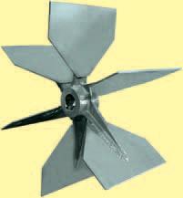
Disk fans require no duct work, or static pressure. The blades of disk fans are flat and set at an oblique angle.
Air is picked up by the leading edge of the blade and accelerated. It is then discharged from the trailing edge of the fan, as shown in the movie below.
Propeller
General Information
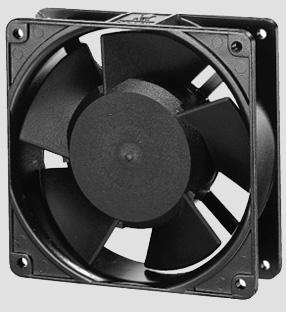
Propeller fans serve a different purpose than centrifugal fans. They are most often used to improve gas circulation when no duct work or static pressure is needed.
As the animation below shows, air enters and leaves the fan axially. The gas is picked up by the leading edge, accelerates, and is discharged from the trailing edge.
Equipment Design
The blades of a propeller fan are warped to improve gas circulation.
Acknowledgements
- EZ Fan & Blower Company, Los Angeles, CA
- Lau Industries, Dayton, OH.
- The New York Blower Company, Willowbrook, IL
References
- Baumeister, Theodore, Jr. Fans . New York: McGraw-Hill Inc., 1935. Print.
- Bleier, Frank P. Fan Handbook: Selection, Application, and Design . New York: McGraw-Hill, 1998. Print.
- Eck, Braun. Fans . Oxford: Pergamon Press, 1973. Print.
- Jenkins, Scott. “Facts At Your Fingertips: Fans and Blowers.” Chemical Engineering. October 2012: 25 Print.
- Perry, Robert H., and Don W. Green. Perry’s Chemical Engineers’ Handbook. 7th ed. New York: McGraw-Hill Inc., 1998: 10-45 – 10-46. Print.
Developers
- Sam Catalano
- Kelsey Kaplan
- Thomas Plegue