
Fluidized bed reactors (FBR) are catalytic reactors in which the catalyst is fluidized within the reactor.
General Information
Fluidized bed reactors are heterogeneous catalytic reactors in which the mass of catalyst is fluidized. This allows for extensive mixing in all directions. A result of the mixing is excellent temperature stability and increased mass transfer and reaction rates.
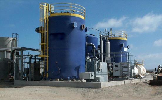
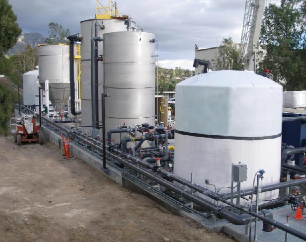
Fluidized bed reactors are capable of handling large amounts of feed and catalyst. Pictured below is an FBR used for treating aniline-and nitrobenzene-contaminated wastewater.
Equipment Design
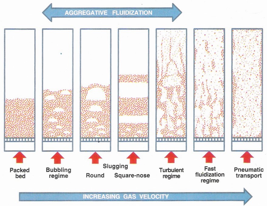
The movie below shows the operation of a fluidized bed reactor. Before the reactor is started the catalyst pellets lie on a grate at the bottom of the reactor. Reactants are pumped into the reactor through a distributor continuously, causing the bed to become fluidized. The bed’s behavior after initial fluidization depends on the state of the reactant. If it is a liquid, the bed expands uniformly with increased upward flow of the reactant. This is called homogenous fluidization. If the reactant is a gas, the bed will be non-uniform because the gas forms bubbles in the bed, resulting in aggregative fluidization. Sometimes these bubbles in coarse materials can grow larger than two-thirds of the bed’s diameter, which can cause slugging. Slugging can result in variable pressures, vibrations in the bed, and heat transfer reductions. Increasing the velocity of the gas leads to a turbulent regime, as shown below. In the fast fluidization regime, the bed surface starts to disappear. Increasing the gas velocity further results in pneumatic transport, in which the bed is completely removed and the particles are uniformly spaced in the fluid. During this process the reactants react due to the presence of the catalyst pellets, forming products that are removed continuously.
Fluidized bed reactors are generally very large. They must be designed so that the fluid flow rate is sufficient to suspend the catalyst particles. The particles typically range in size from 10 – 300 microns.
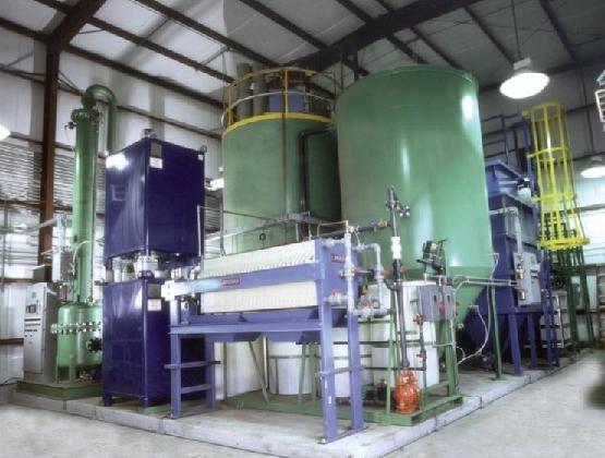
When designing a fluidized bed reactor, the catalyst life must also be taken into account. Most fluidized bed reactors, such as the one shown here have a separate compartment to regenerate the catalyst.
Usage Examples
Fluidized bed reactors are commonly used in catalytic cracking processes. They are also used in the oxidation of naphthalene to phthalic anhydride, roasting of sulfide ores, coking of petroleum residues, and the calcination of limestone. They are often used when there is a need for large amounts of heat input or output, or when closely controlled temperatures are required.
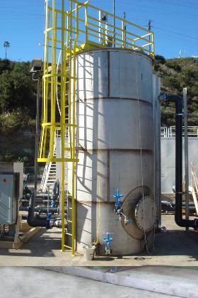
The fluidized bed reactors below are used in NASA’s Jet Propulsion Laboratory for the removal of perchlorate and chlorinated solvent from groundwater. The system can remove perchlorate from up to 350 gallons of groundwater per minute.
Advantages
- Even temperature distribution eliminates hot spots.
- Catalyst is easily replaced or regenerated.
- Allows for continuous, automatically controlled operations.
- More efficient contacting of gas and solid than in other catalytic reactors.
Disadvantages
- Expensive to construct and maintain.
- Erosion of reactor walls may occur.
- Regeneration equipment for catalyst is expensive.
- Catalyst may be deactivated.
- Can’t be used with catalyst solids that won’t flow freely.
- Large pressure drop.
- Attrition, break-up of catalyst pellets due to impact against reactor walls, can occur.
Acknowledgements
References
- Dhodapkar, Shrikant V., Klinzing, George E., and Zaltash, Abdolreza. “A Primer on Gas-Solids Fluidization” Chemical Engineering. August 2012: 38-47 Print.
- Fogler, Scott H. Elements of Chemical Reaction Engineering. 3rd ed. Englewood Cliffs, NJ: Prentice-Hall, 1998. Print.
- Hill, Charles G., Jr. An Introduction to Chemical Engineering Kinetics and Reactor Design. New York: John Wiley & Sons, Inc. 1977. Print.
- Kunii, Daizo, and Levenspiel, Octave. Fluidization Engineering New York: Robert E. Krieger Publishing Co., 1977. Print.
- Perry, Robert H., and Don W. Green. Perry’s Chemical Engineers’ Handbook. 7th ed. New York: McGraw-Hill Inc., 1997. Print.
- Trambouze, Pierre, Van Landeghem, Hugo, and Wauquier, Jean-Pierre. Chemical Reactors. Houston: Gulf Publishing Company, 1988. Print.
- Walas, Stanley M. Chemical Process Equipment: Selection and Design. Boston: Butterworth-Heinemann, 1990. Print.
- Walas, Stanley M. Reaction Kinetics for Chemical Engineers. New York: McGraw-Hill Inc., 1959. Print.
Developers
- Sam Catalano
- Alex Wozniak
- Kelsey Kaplan
- Thomas Plegue