
Fuel cells produce hydrogen-based energy capable of powering a wide variety of devices such as cell phones, cars, combined heat and power systems, and the space shuttle.

Proton Exchange Membrane
Also called solid polymer fuel cells (SPFC), proton exchange membrane fuel cells use hydrogen and oxygen to produce water, electricity, and heat.
General Information
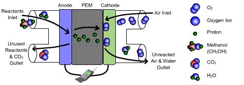
A proton exchange membrane fuel cell (PEMFC) consists of 5 basic elements
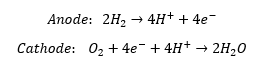
These reactions take place at low temperatures, so catalysts such as platinum are necessary. The oxygen used can be either pure or as a part of the air, but the hydrogen should be a pure stream.
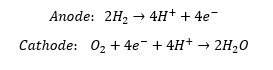
The fuel cell operates according to the following reactions:
Equipment Design
The electrolyte, or membrane, in a PEMFC, is comprised of both hydrophobic and hydrophilic regions. The hydrophobic regions provide support to the electrolyte. The hydrophilic regions help to transport protons from the anode to the cathode by holding water and becoming acidic. The protons move through these regions and cross the electrolyte, but the electrons get repulsed. Instead, they pass as a current through a load to get to the cathode.
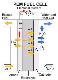
It is important that the electrolyte stay hydrated to ensure that the protons can move to the cathode. In order to keep the electrode hydrated (but not overly hydrated to avoid flooding), the relative humidity inside the PEM should be maintained at 80-99%.

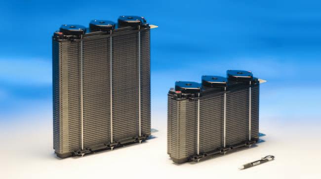
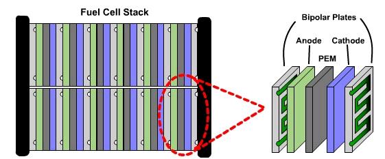
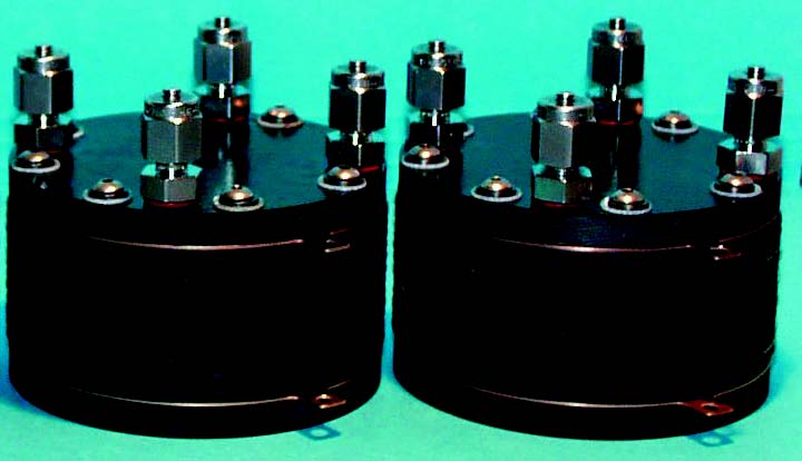
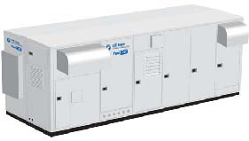
The power output of one membrane-electrode assembly (MEA) is very low. To make fuel cells a viable source of energy, many MEAs are combined in what is known as a fuel cell stack, as shown below.
Usage Examples
Proton exchange membrane fuel cells have many potential applications, mostly due to their compact membrane electrode assemblies and low operating temperatures. These applications include integrating PEMFCs into vehicles, stationary power generators, combined heat and power systems (CHPs), as well as portable electronics. Pictured below is a Ford Focus that has been modified to use zero-emission PEMFCs.

PEMFC technology is being explored to be used in space vehicles, such as the Mars Flyer pictured below, and for aircraft acceleration and power systems. The fuel cells can also be used for producing drinking water for spacecraft crews, as well as electricity for spacesuits, airplanes, uninhabited air vehicles, and reusable launch vehicles.

Advantages
- No corrosive fluids needed.
- Quick startup.
- Can be very compact due to their thin electrolytes.
- Suitable for a wide range of power requirements.
- May operate in any orientation.
- Low temperature.
Disadvantages
- Very sensitive to carbon monoxide and sulfur poisoning.
- Platinum catalyst is needed.
- Sensitive to low humidity.
- Manufacturing and sealing is complicated.
- Requires pure H 2 gas, which is challenging to store.
Alkaline
As their name suggests, alkaline fuel cells use an alkaline electrolyte, usually KOH. They are unique because OH – ions pass through this electrolyte instead of protons. AFCs were first used by NASA in the 1960s for the Apollo missions.

General Information
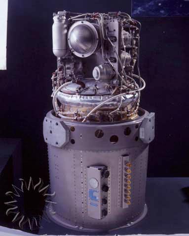
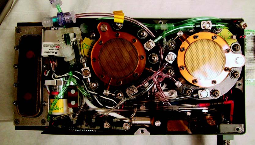
An alkaline fuel cell (AFC) is similar to a proton exchange membrane fuel cell (PEMFC) in that oxygen and hydrogen are used to produce water, electricity, and heat. In an AFC, OH – ions pass through the electrolyte, and water is both produced and used. AFCs are known for operating with high efficiency and at relatively low temperatures. However, the reaction environment must be CO-free because this gas will react with the alkaline electrolyte. The AFC pictured below is the model that powered the Apollo Command and Service Module, pictured above.
Equipment Design
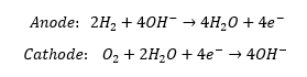
Alkaline fuel cells operate according to the following reactions:
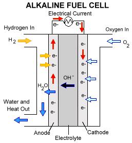
As the picture below shows, this fuel cell operates on the same principles as the proton exchange membrane fuel cell (PEM). However, here the water is produced at the anode, as opposed to at the cathode as in a PEM.
Usage Examples
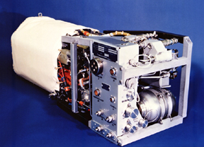
The relatively simple design of alkaline fuel cells has made them the preferred choice of NASA for their shuttles. The early Apollo missions were the first to employ this technology, and to date, the Space Shuttle still uses alkaline fuel cell systems, such as the one shown below, to generate power and drinking water. As other fuel cell technologies are becoming more developed, alkaline fuel cells are proving to be outdated and less practical compared to the cheaper, more efficient newer technologies.
Advantages
- Employs a relatively simple design.
- Wide range of operating temperatures and pressures
- Electrodes, particularly the cathode, do not require precious metals
- Electrolytes cost far less than other fuel cells
Disadvantages
- Low power density.
- Carbon dioxide degenerates the electrolyte, causing performance to decrease.
- Works best on a pure oxygen supply, as opposed to air.
Direct Methanol
Direct methanol fuel cells get their name from the fuel they use, which is methanol that is fed directly to the anode of the membrane electrode assembly.
General Information
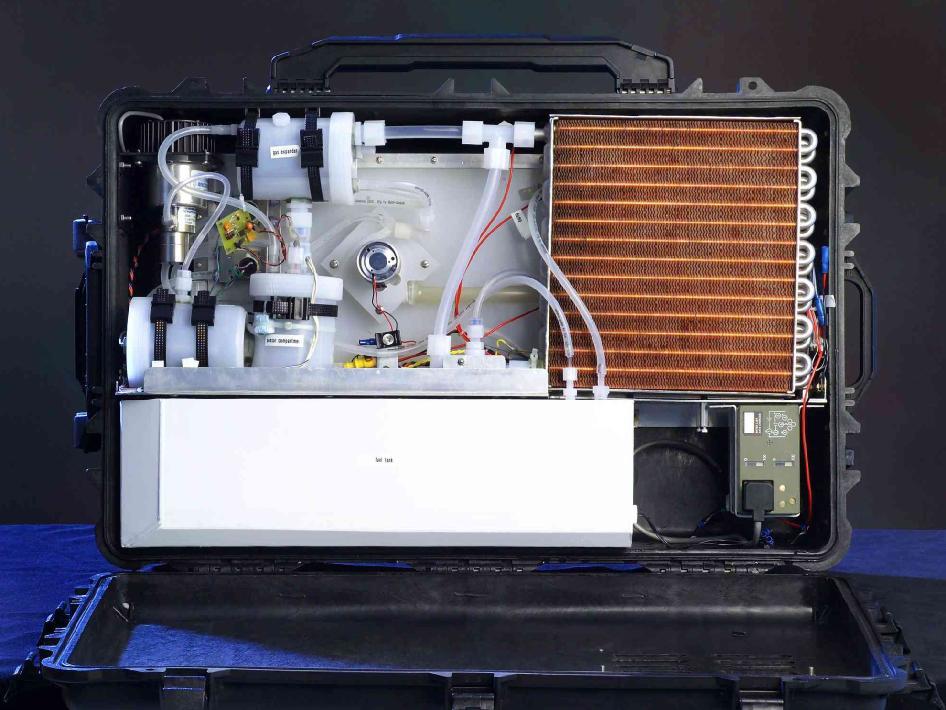
Direct methanol fuel cells use liquid methanol, water, and oxygen to produce water, carbon dioxide, heat, and electricity. DMFCs are similar to PEMFCs in that protons pass through the electrolyte. These fuel cells run at relatively low temperatures and have low power production. Internal components of a direct methanol system are pictured below.
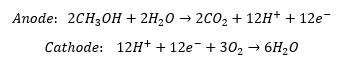
The material reactions that take place are:
Equipment Design
Direct methanol fuel cells (DMFC) are often very similar to proton exchange membrane fuel cells (PEMFC). In a DMFC, methanol and water are fed into the anode, while oxygen or air is fed into the cathode. In the anode, methanol is oxidized using a platinum-ruthenium catalyst. Problems in a DMFC can occur because this catalyst is poisoned by some of the intermediate products formed in methanol oxidation. In the cathode, oxygen is split into ions by means of a platinum catalyst and reacts with the protons to produce water. Both electrodes consist of a gas diffusion layer covering the catalysts.
The electrolyte in a DMFC is often composed of polytetrafluoroethylene (PTFE) with sulfonated side chains. PTFE is a very stable structure, but it is extremely hydrophobic. The sulfonated side chains, on the other hand, are very hydrophilic. The electrolyte will therefore be comprised of both hydrophobic and hydrophilic regions.
The hydrophilic regions hold water and become acidic, allowing the protons to cross from the anode through the electrolyte to the cathode. The electrons, on the other hand, pass as a current through a load to get to the cathode. The carbon dioxide formed from the methanol oxidation reaction is diffused back through the gas diffusion layer of the anode and exits the fuel cell.
It is important that the electrolyte stay hydrated to ensure that the protons get passed over to the cathode. In order to keep the electrode hydrated (but not overly hydrated to avoid flooding), the relative humidity inside the fuel cell should be maintained at 80-99%. In DMFC, a crossover of the methanol to the cathode before it oxidizes can also occur, reducing the efficiency of the fuel cell.
Usage Examples
Direct methanol fuel cells may prove most useful in situations that call for low power-density but high energy-density. In other words, DMFCs are suitable for devices that only require a few watts to function, but are expected to run for days at a time, such as cell phones and portable music players. Conversely, automobiles are an unlikely application of this technology because of their high power consumption.

Advantages
- Methanol can be refueled quickly and simply.
- Methanol is arguably the most efficient carrier of hydrogen.
- The simplicity of methanol storage drastically reduces the weight of the system.
- Ideal for low power-density, but high energy-density applications.
- The lack of an external reformer lowers cost and increases efficiency.
Disadvantages
- Fuel can cross electrolyte without reacting, reducing efficiency.
- Low power-density.
- Methanol can corrode various parts of the fuel cell.
- Methanol is toxic and flammable, much like gasoline.
- Some of the intermediate products involved in methanol oxidation can poison the catalyst.
Medium and High Temperature
Phosphoric Acid
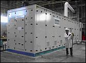
Phosphoric acid fuel cells are unique because they were the first type of fuel cell produced commercially. The unit pictured below is located outside of a supermarket in New York.
General Information
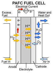
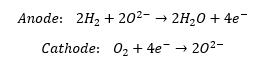
Like any other fuel cell, the phosphoric acid fuel cell (PAFC) uses oxygen and hydrogen to produce water, electricity, and heat. The material reactions that take place are as follows:
Usually, the hydrogen for the reactions comes from reformed natural gas, and the oxygen comes from an air feed stream. Because the PAFC operates at temperatures around 220°C, platinum is still required as a catalyst. The PAFC is more resistant, however, to carbon monoxide poisoning than other fuel cells that operate at lower temperatures.
Equipment Design
Hydrogen from reformed fuel is fed to the anode of the PAFC, while oxygen or air is fed to the cathode. In the electrodes, these two diatomic gases are split into ions by means of a catalyst. The phosphoric acid provides the medium to transport protons from the anode to the cathode. The protons move through these acidic regions to cross the electrolyte, while the electrons are repulsed and pass as current through a load to get to the cathode.
Usage Examples
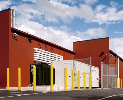
Phosphoric acid fuel cells are most suitable for combined heat and power systems, known as CHPs, in which heat produced in the system is reused. Some ways that a CHP uses this heat include to heat processes within the system and to heat nearby buildings. The steam produced in this type of system can also be used to drive turbines and therefore produce more electricity. Using a PAFC as a CHP enables the system to reach efficiencies up to 85%. The system shown is a 250 kW system used by the New York Police Department.

Advantages
- The heat produced in the fuel cell can be used to heat other processes.
- Relatively low temperatures do not require exotic materials
- The steam produced can be used to drive turbines and produce more electricity in a very efficient manner.
- The design is more tolerant of impurities than earlier fuel cell designs.
Disadvantages
- External fuel reforming is necessary.
- High capital costs compared to other energy-generating systems.
- Bulky
- Requires a platinum catalyst.
Solid Oxide
Solid Oxide Fuel Cells are characterized by their solid metal oxide electrolyte that allows these fuel cells to operate at temperatures up to 1000°C.
General Information
The SOFC uses oxygen and hydrogen to produce water, electricity, and heat:
This results in a stream of electrons that serve as a source of power.
The solid oxide ceramic electrolytes, pictured here, can withstand operating temperatures between 600 and 1000°C, such that high reaction rates are possible without the use of precious-metal catalysts. In addition, the SOFC can use natural gas directly.
Equipment Design
Solid oxide fuel cells come in many geometries, of which the tubular design shown here is the most prevalent. This design is often chosen because it is easier to seal than the plates found in other fuel cells.
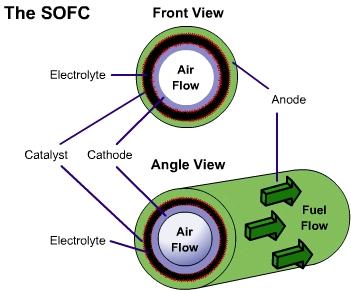
There are two electrodes in every unit of a SOFC, an anode, and a cathode. Air is fed through the center of the tube, while fuel is fed into the outer tube regions, where it is reformed to obtain hydrogen. Between these electrodes lies the solid oxide electrolyte that gives this fuel cell its name.
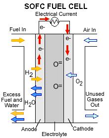
As seen in the close-up image, oxygen is exposed to the cathode, where it breaks up to produce oxygen ions. These ions pass through the vacancies in a solid ceramic electrolyte to get to the anode. The hydrogen is broken apart into ions on the anode and combines with the oxygen ions to produce water. The water then diffuses out of the anode and leaves with any unspent fuel. Splitting apart the hydrogen molecules produces electrons. These electrons are routed through an external load, and then returned via the bridge to the cathode, where they are consumed when the oxygen is split apart.
Usage Examples
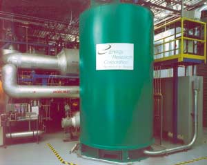
Since solid oxide fuel cells are tolerant of impurities and do not require an external reformer they have a wide range of applications. Some SOFCs operate on the methane gas produced in wastewater treatment facilities. SOFCs are also well suited for combined heat and power systems (CHPs), such as the one shown below.

A CHP is a system that uses the heat produced in the system rather than letting it go to waste. CHP may use this heat for processes within the system or to warm nearby buildings. The heat may also produce steam, which can be used to drive turbines and therefore produce more electricity. SOFCs used in CHP systems may reach efficiencies as high as 85%.
Advantages
- Mechanically simple – it is a solid-state device.
- Can be fed natural gas directly.
- No precious metals required for catalysis.
- The heat produced in the fuel cell can be used to heat other processes
- The steam produced can be used to drive turbines and produce more electricity.
- The design is more tolerant of impurities than other fuel cell designs.
Disadvantages
- The high operating temperature requires exotic materials, such as ceramics.
- The ceramic materials used are expensive to manufacture and fragile.
- Manufacturing costs are high compared to gas turbines and coal power plants.
Molten Carbonate
Molten carbonate fuel cells are unique because the electrolyte used is a hot, corrosive liquid contained in a ceramic matrix.
General Information
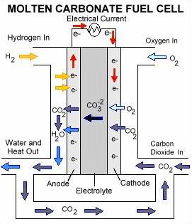
The MCFC uses hydrogen, oxygen, and carbon dioxide to make water, electricity, and heat. Reaction temperatures of 650°C make MCFCs very efficient and allow for nickel to be used as the catalyst. The high temperatures also make it possible to use natural gases directly. The material reactions that take place are as follows:
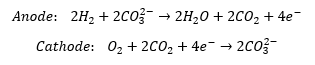

Equipment Design
In the cathode, oxygen is split into ions by means of a catalyst. The ions react with carbon dioxide and electrons to form carbonate ions. These ions diffuse through the molten electrolyte toward the anode. Each carbonate ion reacts with a hydrogen molecule to form water, carbon dioxide, and free electrons. The electrons travel through an external load, such as a house, before returning to the cathode. Typically, the water is separated and vented from the fuel cell. The carbon dioxide is directed back to the cathode where it will react with oxygen ions, restarting the whole process.
Usage Examples
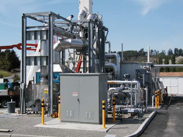
Molten carbonate fuel cells produce high-temperature exhaust, making them suitable for combined heat and power systems (CHPs). A CHP is a system that uses the heat produced in the system rather than letting it go to waste. The heat is used for processes within the system, to heat nearby buildings, or to produce steam. The steam produced in this type of system can then be used to drive turbines and therefore produce more electricity. Using the MCFC as a CHP makes the system very efficient, with possible efficiencies up to 85%. The heat recovery equipment pictured below recycles the excess heat generated by an MCFC that operates on methane produced at a sewage treatment facility.
Advantages
- The nickel used is a relatively cheap catalyst.
- The electrochemical reactions proceed quickly.
- Can be used as a combined heat and power system.
- The steam produced can be used to drive turbines and produce more electricity.
- The design is more tolerant of impurities than lower temperature fuel cells.
- Works at higher efficiencies and therefore produces less carbon dioxide.
Disadvantages
- Degradation of the components, especially electrolyte, can occur.
- High temperatures require exotic construction materials, increased cost.
Acknowledgments
- Ballard Power Systems Inc., British Columbia, Canada
- King County Fuel Cell Demonstration Project
- Los Alamos National Laboratory (LANL)
- NASA
- New York Power Authority, White Plains, N.Y.
- U.S. Department of Energy
- U.S. Department of Energy EERE
- UTC Power Corporation, South Windsor, CT
References
- “Collecting the History of Molten Carbonate Fuel Cells.” National Museum of American History. Smithsonian Institution, May 2001. Web. June 2011.
- Dohle, H., J. Divisek, and R. Jung. “Process Engineering of the Direct Methanol Fuel Cell.” Journal of Power Sources 86 (2000): 469-77. Print.
- Fitzgerald, Justin, and Nancy O’Bryan. “Fuel Cells: A Better Energy Source for Earth and Space.”   Glenn Research Center. NASA, Feb. 2005. Web. 15 Dec. 2010.
- Gasteiger, Hubert, Arnold Lamm, and Wolf Vielstich. Handbook of Fuel Cells: Fundamentals, Technology, Applications. Chichester: Wiley, 2003. Print
- Hoogers, G. “Fuel Cells for Cogeneration.” COSPP.com. Cogeneration & On-Site Power Production, 01 July 2003. Web. June 2011. http://www.cospp.com/articles/2003/07/fuel-cells-for-cogeneration.html
- Larminie, James, and Andrew Dicks. Fuel Cell Systems Explained. Chichester: Wiley, 2009. Print.
- “Molten Carbonate Fuel Cell Technology.” Office of Fossil Energy. U.S. Dept. of Energy, 31 Jan. 2011. Web. June 2011.
- “Phosphoric Acid Fuel Cell Technology.” Office of Fossil Energy. U.S. Dept. of Energy, 31 Jan. 2011. Web. 03 June 2011.
- “The Principle Behind the Technology.” Siemens Energy. Siemens AG, 2010. Web. June 2011.
- “Tubular Solid Oxide Fuel Cell Technology.” Office of Fossil Energy. U.S. Dept. of Energy, 09 Feb. 2011. Web. June 2011.
- “Types of Fuel Cells.” Energy Efficiency and Renewable Energy. U.S. Dept. of Energy, 08 Mar. 2011. Web. June 2011.
- U.S. Dept. of Energy. Office of Fossil Energy. Fuel Cell Handbook (Seventh Edition). By EG&G Technical Services, Inc. National Energy Technology Laboratory, Nov. 2004. Web. June 2011.
Developers
- Theresa Czech
- Rob Main
- Kelsey Kaplan