Plug, or tubular, flow reactors consist of a hollow pipe or tube through which reactants flow. Pictured below is a plug flow reactor in the form of a tube wrapped around an acrylic mold that is encased in a tank. Water at a controlled temperature is circulated through the tank to maintain a constant reactant temperature.

(Copyright Armfield Limited, Ringwood, UK)
General Information
Plug flow reactors, also known as tubular reactors, consist of a cylindrical pipe with openings on each end for reactants and products to flow through.
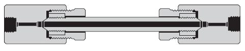
(Copyright High Pressure Equipment Co., Erie, PA)
Plug flow reactors are usually operated at steady-state. Reactants are continually consumed as they flow down the length of the reactor.
Equipment Design
The movie below shows the operation of a plug flow reactor. Plugs of reactants are continuously fed into the reactor from the left. As the plug flows down the reactor the reaction takes place, resulting in an axial concentration gradient. Products and unreacted reactants flow out of the reactor continuously.
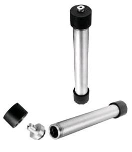
Plug flow reactors may be configured as one long tube or a number of shorter tubes. They range in diameter from a few centimeters to several meters. The choice of diameter is based on construction cost, pumping cost, the desired residence time, and heat transfer needs. Typically, long small diameter tubes are used with high reaction rates, and larger diameter tubes are used with slow reaction rates.
(Copyright High Pressure Equipment Co., Erie, PA)
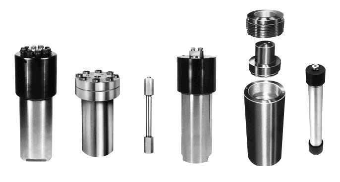
The picture below shows a disassembled tubular reactor.
(Copyright High Pressure Equipment Co., Erie, PA)
Usage Examples
Plug flow reactors have a wide variety of applications in either gas or liquid phase systems. Common industrial uses of tubular reactors are in gasoline production, oil cracking, synthesis of ammonia from its elements, and the oxidation of sulfur dioxide to sulfur trioxide. Pictured below is a tubular reactor used in research on the oxidation of nitrogen compounds. It reaches temperatures of 800 – 1100°C.
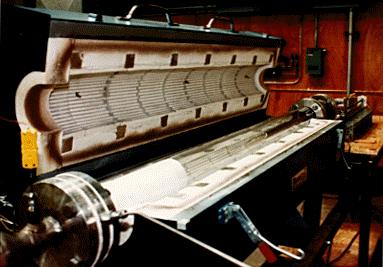
(Copyright Robert Hesketh, Rowan University, Glassboro, NJ)
Tubular reactors can also be used as bioreactors or for small-scale production. The tubular bioreactor shown below is used for the production of algae. The algae is then compressed and dried and can be used as feed for a biodiesel reactor.
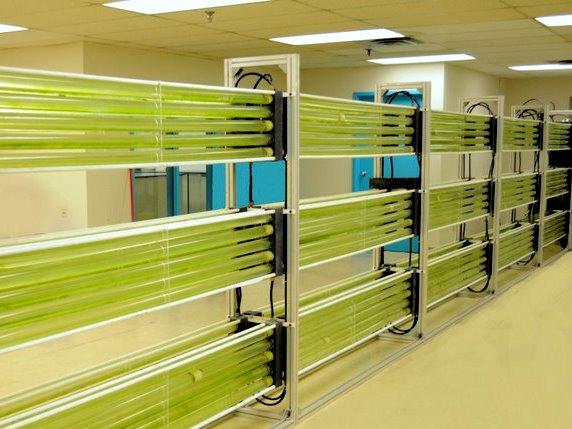
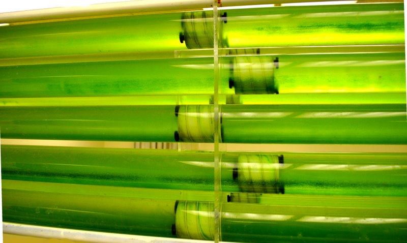
(Copyright W2 Energy, Inc., Carson City, NV)
Advantages
- Easily maintained since there are no moving parts.
- High conversion rate per reactor volume.
- Mechanically simple.
- Unvarying product quality.
- Good for studying rapid reactions.
- Efficient use of reactor volume.
- Good for large capacity processes.
- Low pressure drops.
- Tubes are easy to clean.
Disadvantages
- Reactor temperature difficult to control.
- Hot spots may occur within reactor when used for exothermic reactions.
- Difficult to control due to temperature and composition variations.
Acknowledgments
- Armfield Limited, Ringwood, UK
- High Pressure Equipment Co., Erie, PA
- Robert Hesketh, Rowan University, Glassboro, NJ
- W2 Energy, Inc., Carson City, NV
References
- Ashe, Robert. “From Batch to Continuous Processing.” Chemical Engineering. October 2012: 34-40. Print.
- Fogler, Scott H. Elements of Chemical Reaction Engineering. 3rd ed. Englewood Cliffs, NJ: Prentice-Hall, 1998. Print.
- Hill, Charles G., Jr. An Introduction to Chemical Engineering Kinetics and Reactor Design. New York: John Wiley & Sons, Inc. 1977. Print.
- Perry, Robert H., and Don W. Green. Perry’s Chemical Engineers’ Handbook. 7th ed. New York: McGraw-Hill Inc., 1997: 7-19 – 7-20. Print.
- Trambouze, Pierre, Van Landeghem, Hugo, and Wauquier, Jean-Pierre. Chemical Reactors. Houston: Gulf Publishing Company, 1988. Print.
- Walas, Stanley M. Chemical Process Equipment: Selection and Design. Boston: Butterworth-Heinemann, 1990. Print.
- Walas, Stanley M. Reaction Kinetics for Chemical Engineers. New York: McGraw-Hill Inc., 1959. Print.
Developers
- Sam Catalano
- Alex Wozniak
- Kelsey Kaplan
- Thomas Plegue