Velocity flowmeters are popular because they give a direct measure of fluid velocity, the characteristic most commonly associated with flow rate. These flowmeters, however, are among the most sensitive to process conditions.
Since velocity flowmeters operate under the assumption of a constant velocity profile, they are inaccurate for flows in the laminar regime. This inaccuracy occurs because there is a large difference between the fluid velocity at the wall and at the center of the pipe. This property makes velocity flowmeters especially sensitive to piping geometry and Reynolds number.
The types of velocity flow meters found in the table of contents below generally overs general information, equipment design, usage examples, and advantages/disadvantages.
Turbine & Paddlewheel
Turbine meters and paddlewheel meters are among the most versatile flowmeters.
General Information
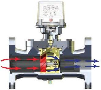
When fluid flows past a turbine meter, such as the one pictured below, the meter’s vaned rotor rotates. The same occurs in a paddlewheel, except the paddlewheel’s blades are perpendicular to the direction of flow. In both cases, the angular velocity of the rotor is proportional to the velocity of the fluid
Equipment Design
A magnetic pickup coil is mounted outside the pipe. The turbine or paddlewheel blades are made of or contain magnetic material. As the fluid flows and each blade passes by the coil, the magnetic flux through the coil changes, causing a voltage pulse. A sensor measures the pulse rate and from that determines the flow rate.
To obtain the constant velocity profile necessary for an accurate measurement, turbine and paddlewheel meters require a straight section of pipe upstream and downstream of the flow meter. Elbows, T’s, valves, and changes in pipe diameter all cause distortions in the velocity profile. If there are no long straight sections of pipe available, correction devices can be installed upstream to help straighten the velocity profile and obtain an accurate reading. Options include straightening vanes or bundled tubes.
Usage Examples
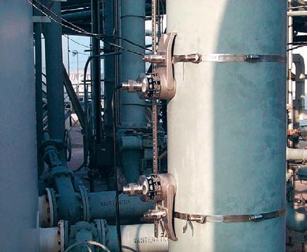
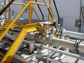
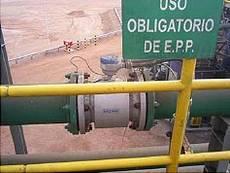
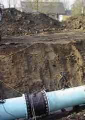
Turbine meters and paddlewheels are used in the same types of applications. Below left is a petroleum pipeline that utilizes an insertion turbine flowmeter for leak detection. The picture on the right is of a petroleum plant in India that is using turbine meters for loading light hydrocarbon products into road tankers and rail cars. In addition to metering chemicals, water, and fuel, they are used in oil drilling operations or for metering cryogenic gases.
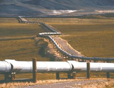
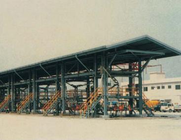
(Copyright Hoffer Flow Controls, Inc., Elizabeth City, NC)
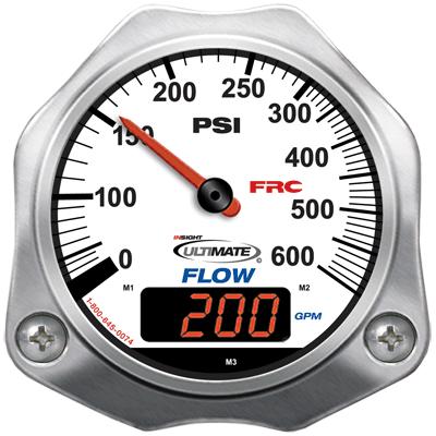
The turbine meter below is used in firefighting equipment.
Advantages
- One meter can be manufactured to handle a wide range of flow rates.
- Turbine meters are highly accurate.
- Low cost.
- May be constructed of a variety of materials to handle a variety of fluids.
- Paddlewheels provide a more cost-effective alternative when less accuracy is required or with viscous flow.
- Low mass of rotor allows rapid response and ability to measure pulse flow.
Disadvantages
- Can cause large pressure drops.
- Flashing or bubble formation may occur if the downstream pressure of a liquid stream is too low.
- Require lengths of straight pipe upstream and downstream.
Ultrasonic
Ultrasonic flowmeters use sound waves to measure flow rate.
General Information
The principle behind ultrasonic flowmeters is the variation between transmitted and received sound waves as a result of fluid flow. Two types of ultrasonic flowmeters are commonly used today: time-of-travel (or transit-time) and Doppler.
Equipment Design
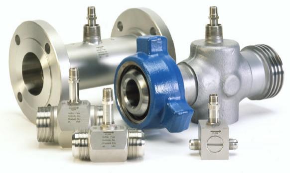
Ultrasonic flowmeters send sound waves through a stream via transducers, a variety of which are shown here. The returning sound wave provides information about the stream’s flow rate.
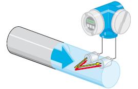
Time-of-travel ultrasonic meters consist of two opposing transducers installed inside a pipe, one upstream of the other. The upstream transducer sends a sound wave downstream to the other transducer, and vice versa. The difference between the velocity of sound with the flow and against the flow is directly proportional to the velocity of the stream. When no fluid is flowing, the upstream and downstream transit times are the same. When fluid is flowing, the transit time downstream is less than the transit time upstream.
Doppler flowmeters continuously send sound waves at a constant frequency through pipe walls via a sensor mounted on the outside of the pipe. Particles or bubbles in the stream reflect the sound waves back to the sensor. If the fluid is flowing, the sound waves come back at a different frequency. The frequency shift is directly proportional to the velocity of the stream.
Usage Examples
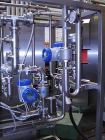
The time-of-travel sonic meter below utilizes sensors that clamp on the outside of existing pipes. They are versatile and can be used in a wide variety of applications.
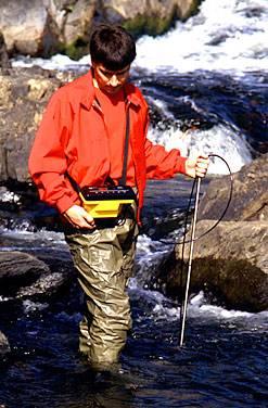
The ultrasonic Doppler sensor shown below on the left is used to measure flow in open channels such as sewer pipes, canals, and rivers. Ultrasonic flowmeters are also commonly found in the food and beverage and chemical processing industries. Oil, oil products, grease, and water/oil mixtures can be metered by ultrasonic meters, such as the installed meter shown below. Ultrasonic meters are often used in crude oil refining applications.
Advantages
- Non-invasive, so no pressure drop
- Measures flow of fluids and slurries that ordinarily cause damage to conventional sensors
- Responds quickly to changes in velocity
- Eliminates local mechanical and electrical noise, permitting use in a variety of locations
- Works with a variety of pipe sizes and flow conditions
- Accommodates flow in either direction
- Measures independently of temperature, pressure, density, viscosity, and electrical conductivity
- Non-contact, lack of moving parts greatly reduce maintenance requirements and sensor fouling
- Easy installation.
Disadvantages
- Doppler: can’t measure gas flow
- Time-of-travel: requires relatively clean fluid
- Excess solids or entrained gases may block ultrasonic pulses
- Requires steady flow, can’t handle wide and/or rapid fluctuations
Electromagnetic
Electromagnetic flowmeters, commonly called mag meters, are used to meter conductive fluids.
General Information
The operation of electromagnetic flowmeters is based on Farraday’s Law. When a conductor moves at right angles to a magnetic field, a voltage difference is induced in the conductor that is proportional to the conductor’s velocity.
The two types of electromagnetic flowmeters, wafer-style and insertion-style, use different methods of creating the magnetic field through which the conductive fluid flows.
Equipment Design
Wafer-style flowmeters establish a magnetic field across the entire cross-section of a pipe from outside the pipe. This design allows the magnetic field to be evenly exposed to flow conditions at all points in the pipe cross-section.
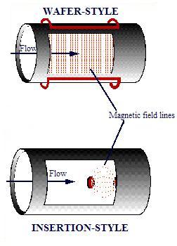
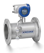
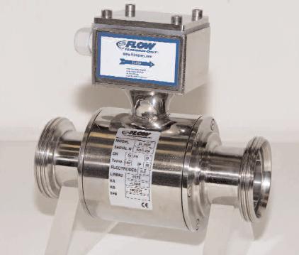
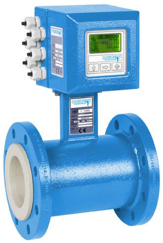
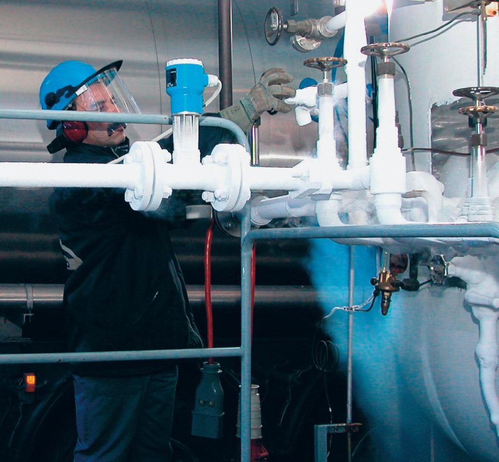
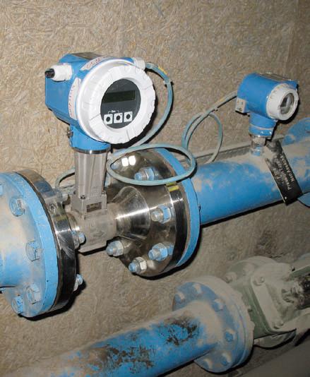
Insertion-style flowmeters, such as the one below, use sensors inserted into the pipe to generate the magnetic field. Electrodes in the sensors detect the voltage across the liquid, which is used to determine the flow rate.
Electromagnetic flowmeters can handle changes in the liquid’s conductivity as long as the change is uniform through the flow and not below the minimum conductivity threshold of the meter. The meter must also be grounded and the measuring tube lined with or made of insulating material to prevent current flow through the liquid, pipe, and other surrounding equipment.
A number of factors affect the conductivity of liquids and must be carefully evaluated. Most importantly, conductivity is a function of temperature and concentration, but how each affects conductivity depends on the liquid. Therefore, process conditions must always be known. Unknown impurities also have adverse effects.
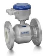
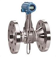
At left is a Teflon® lined meter designed to handle high temperatures. It, like the meter on the right, can measure flow of liquids with conductivities as low as 5 µS/cm.
Usage Examples
Mag meters are used in many industries, including food, beverage, pharmaceutical, chemical, and cosmetic industries. The mag meter pictured below is used to measure the flow of milk and cream.
The bottom left picture shows the use of a mag meter to monitor the flow of copper slurry in a copper ore mining facility. The mag meter is lined to resist the highly abrasive slurry. Pictured below on the right is a mag meter used in drinking water treatment operations. The meter is used to accurately measure the volume of water going to the purification plant.
(Copyright Krohne, Inc., Peabody, MA)
Specially designed electromagnetic flowmeters can be used to measure flow in open channels. Sensors, along with the proper housing are used to create the magnetic field. The entire mechanism can be submerged in a manhole, or stream, as shown below, to monitor flow rate.
Advantages
- Low-pressure drop
- No moving parts means less wear, no routine maintenance
- Insensitive to density, viscosity, pressure, temperature and flow profile
- Usable for a variety of otherwise difficult to meter fluids
- Accurate (error range of 0.5%)
- Relatively low cost
- Measures independently of temperature, pressure, density, viscosity, and electrical conductivity
- Measures forward and reverse flow
- Can be used with pipes of varying sizes
Disadvantages
- Can only meter liquids
- Liquids must be conductive
- Nearby electromagnetic noise causes interference
- Will not work in partially full pipes, even if electrodes are wetted
- Requires lengths of straight pipe upstream and downstream
- Allowing sludges and greasy fluids to flow too slow causes buildup, which affects measurement
Vortex-Shedding
Vortex-shedding meters use the principles of turbulence to measure flow rate.
General Information
When fluid flows past a blunt (non-streamlined) object, turbulence forms at the sides of the object in the form of eddies, or vortices. As the eddies flow downstream, they separate, or shed, from the blunt object and grow in size. These vortices shed alternately from each side of the object and swirl in opposite directions. The rate of shedding and size of the vortices is directly proportional to the flow rate of the fluid. This phenomenon is the same as that which makes a flag flap in the wind.
Equipment Design
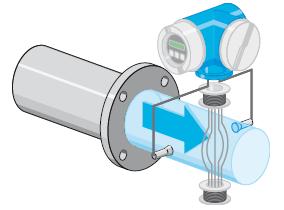
Vortex-shedding flowmeters differ from each other in the type of sensor used to detect the vortices. Some of these flowmeters use a metal sphere or disc that shifts back and forth as the vortices flow past it. A magnetic coil counts the object’s oscillations. A variation on this theme uses a bar that flexes as the vortices pass, as shown below. The frequency at which the bar flexes is proportional to the flow rate.
The second type of sensor includes a vane that waves back and forth as shown on the left. Electronic sensors detect the vane’s motion or the mechanical stress on the vane created by the passing eddies.
Another method of detecting vortices uses a thermistor shown to the right, which is cooled by the vortices. The thermistor’s fluctuating temperature causes changes in its electrical resistance, which are used to detect the vortices and determine the flow rate.
Usage Examples
The vortex meter on the right is lined with Teflon®, making it useful for difficult to handle or easily contaminated materials. Vortex meters can universally monitor steam, gas, and liquid flows as long as the fluid is turbulent. They are often used in industries that involve a wide variety of fluids such as chemical and petrochemical industries.
(Copyright Endress+Hauser, Inc., Greenwood, IN)
Advantages
- Accurate regardless of temperature, pressure, density and viscosity when flow is turbulent.
- Suitable for measuring liquids, gases and steam.
- Excellent for metering steam flow.
Disadvantages
- Flow must be turbulent.
- Ineffective for slurries and viscous flow.
Acknowledgements
- Emerson Process Management, Chanhassen, MN
- Endress+Hauser, Inc., Greenwood, IN
- Fire Research Corporation, Nesconset, NY
- FTI Flow Technology Inc., Tempe, AZ
- Hach Company, Loveland, CO
- Hoffer Flow Controls, Inc., Elizabeth City, NC
- IMAC Systems, Inc., Tullytown, PA
- Krohne, Inc., Peabody, MA
References
- Digiacomo, Ronald W. “Measuring Flow.” Chemical Engineering. July 2011: 30 – 34.
- Jenkins, Scott. “Selecting Two- and Four-wire Magnetic Flowmeters.” Chemical Engineering. March 2012: 33
- Omega Complete Flow and Level Measurement Handbook and Encyclopedia, Vol. 29. USA: Omega Engineering Inc., 1995: E-3, F-3 – F-8, H-3 – H-6, Z-8, Z-12 – Z-14, Z-18. Print.
- McCabe, Warren L., Smith, Julian C. and Peter Harriot. Unit Operations of Chemical Engineering. New York: McGraw-Hill, 1993: 226 – 228. Print.
- Miller, Richard W. Flow Measurement Engineering Handbook. 3rd ed. New York: McGraw-Hill, 1996: 6.19 -6.27. Print.
- Perry, Robert H., and Don W. Green. Perry’s Chemical Engineers’ Handbook. 7th ed. New York: McGraw-Hill, 1997: 8-48 – 8-49, 10-10 – 10-11. Print.
Developers
- Erica Mauter
- Steve Wesorick
- Matthew Robertson
- Kelsey Kaplan
- Andrea Roberts
- Thomas Plegue
- Fritz Hyde