Pressure control is crucial to any process so that machinery does not rupture or break, as well as preventing harm to any employees. Pressure affects temperature and when left unregulated can lead to numerous disastrous consequences. It is essential that pressure is monitored, and that when pressure exceeds the process pressure range there is a relief system in place to mitigate it. There are many relief mechanisms to regulate pressure, the most common being rupture discs and valves. These mechanisms, coupled with controls, can help mitigate the risks of high pressure in a process.
Pressure control systems are put into place to keep the operating pressures of all equipment below the maximum allowable working pressure (MAWP). If the MAWP is ever exceeded, pressure relief devices relieve pressure and prevent equipment failure. A pressure control system acts on a signal that is sent from a pressure sensor to a pressure controller. After some control calculations based on comparing the desired setpoint pressure to the actual pressure in the equipment, the controller sends a control signal to the pressure control element, which is typically a control valve. The valve opening then changes so that the pressure can better match the setpoint pressure. If this control system were to ever fail, relief devices lower the system pressure. When control or relief valves allow liquids or gases to exit process equipment to maintain a safe operating pressure, this fluid is sent to secondary containment equipment.
Overpressure Risk Factors
Overpressure in process equipment can damage equipment, cause explosions, and injure workers. Risks include runaway reactions, blocked relief paths for process fluid, equipment failure, and excessive heat input. Any situation in which the temperature rapidly increases or the volume of fluid rapidly increases has the potential for overpressure. Runaway reactions can both lead to rapid volume increases and temperature increases in an exothermic reaction. A blocked relief path or exit stream can rapidly increase the pressure in a system as the volume of fluid builds. Process lines also pose a risk as a blocked line can be heated by ambient temperature or sunlight. There are many ways in which equipment failure can result in overpressure. For example, blocked pumps can heat up process fluid circulating within them. If a valve that supplies fluid to a process fails, excess fluid can rapidly enter the equipment, increasing the pressure. Equipment can also receive excessive heat input in a variety of ways, such as systems being heated for too long, the jacket fluid being too hot, or accidental exposure to sunlight or flames.
Pressure Control Equipment
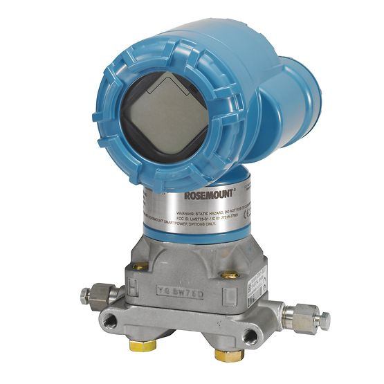
Sensor-Transmitters
Sensor-transmitters measure the pressure in the system and send signals to the controller. The pressure sensor element is usually a diaphragm or membrane with differing pressures on either side of it. The pressure difference results in a deflection that is proportional to the difference and produces an output signal. The transmitter element translates the displacement in the diaphragm to an electric or pneumatic signal that the controller will understand. Other kinds of pressure sensors include piezo devices, capacitors, and potentiometers.
Controllers
The controller compares the signal sent by the sensor transmitter to the desired setpoint pressure and sends a signal to the control valve to vary the flow of a key fluid so as to take the system pressure back to the setpoint value. Within the controller, the signal received from the transmitter is converted from analog to digital for the computer to perform calculations, then back to analog when the control signal is being sent. There are many types of controllers, including on/off, proportional, proportional-integral (PI), and proportional-integral-derivative (PID). In pressure control loops, either proportional or proportional-integral controllers are typically used. PI controllers are used for very fast set-point tracking and adjustments, while proportional controllers are used for adjustments to system parameters over a period of time. For more information on controllers, see the process controls module.
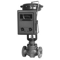
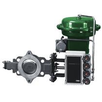
Control Valves
The final control element in a pressure control loop is a control valve, which operates by restricting or permitting the flow of the fluid in a process. An actuator controls the valve based on the signal it receives from a controller. Pneumatic actuators are quite common because they are simpler than electrical or hydraulic actuators. They work by using pressurized air to regulate the valve opening. In a pneumatic actuator, pressure is applied to a diaphragm whose position is determined by an actuator spring on the other side. When the force applied is greater than that of the spring, the attached valve plug will lift from the valve seat and allow more fluid to pass, decreasing the pressure.
Control valves are designed to fail in the completely shut or completely open position, depending on the process. For example, if the valve were handling wastewater being sent to a river, the desired fail position would be closed, because if it remained open it would send contaminated water into the river.
Pressure Relief Equipment
Pressure relief systems are used in high-pressure systems as a backup, should the pressure control system fail. These systems open at a preset pressure so that excess pressure and the contents causing that excess pressure can be relieved from a process. It is also important to have redundancies in a pressure relief system so that failure of any individual piece of equipment does not compromise the safety of the process. Without pressure relief equipment, a failure in pressure control equipment could lead to equipment or pipeline failures, potentially causing an explosion or releasing toxic and flammable substances into the surroundings. The main types of relief devices are spring-operated valves and rupture discs.
Spring-operated Valves
The three main types of spring-operated valves are relief valves, safety valves, and safety relief valves. These spring-operated valves are used for the relief of liquid, gas, and liquid and gas respectively. Safety relief valves function as either relief or safety valves depending on the phase of the fluid present in the process. Spring-operated valves, described in the valve module, open once the operating pressure exceeds the set pressure of the valve and close once the pressure approaches the set pressure again.
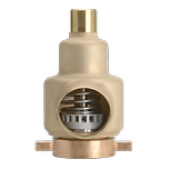
An important aspect of relief device design is the sizing of the equipment. Equipment must be large enough to accommodate possible high-pressure situations, but not so large that other issues can occur. In the case of spring-operated relief valves, chatter is common when the relief area is too large. This occurs when pressure increases and the valve relieves pressure so quickly that it closes again in a short amount of time. If the root of the increasing pressure has not been resolved, the relief device will open and close rapidly, causing damage to it.
Rupture Discs
Rupture discs are designed to burst open at a pressure that is specified by the material properties and construction of the disc.
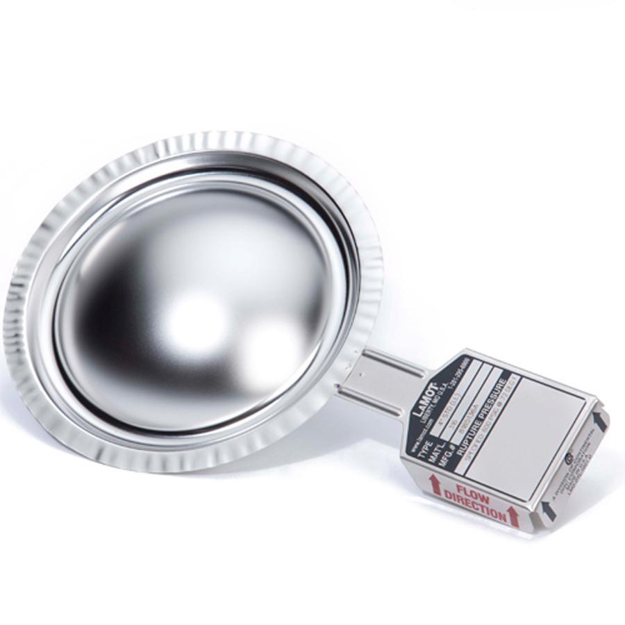
They enhance process safety by relieving fluids, thus lowering operating pressure, and protecting other equipment from corrosive and toxic chemicals. They can also be used to inform process personnel of the pressure at the site of rupture when used in combination with embedded wires that activate alarms when broken or with a pressure gauge. They can be used by themselves or in combination with other forms of pressure relief. If the relief line is meant to remain open once the pressure disc ruptures, a pressure disc can be used by itself. If the relief line needs to close once the pressure has been relieved, a ruptured disc can be used in combination with other forms of pressure relief, and the disc can then be replaced after it bursts. When placed in series with other pressure relief equipment, the goal is to decrease the exposure of relief devices to a corrosive substance, and also to isolate toxic or flammable materials. Rupture discs are commonly used first in series with spring-operated devices, as discs are generally cheaper and limit the contact between a potentially damaging environment and the spring-operated devices.
Secondary Containment Equipment
Secondary containment typically starts with fluid relief at the location of a pressure relief valve or a ruptured disc. The fluid then travels through outlet piping and is treated to leave the process in a safe form. A variety of methods and equipment are used for the treatment of relieving fluid; some of the equipment commonly used for emergency relief is listed below.
Knock-out Drums
Knock-out drums are gravity-driven separators that are used when the relieving fluid contains a considerable amount of hazardous waste in a vapor-liquid mixture.
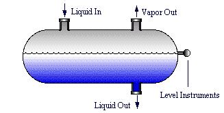
They are typically the first piece of equipment for relieving fluid as they function as a temporary storage tank as well as an intermediate step in a relief system. Knock-out drums capture droplets in the vapor to properly dispose of the vapor and liquid waste separately. By providing sufficient space and decreasing the vapor velocity, large drops of liquid fall out of the vapor phase, then the liquid and vapor phases are sent to different treatment devices. If the effluent has a tendency to congeal, then the tank can be heated to prevent solidification.
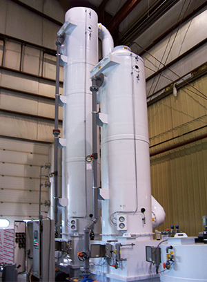
Scrubbers
Once vapor waste has been separated from liquid waste, absorbers are used to treat the vapor so as not to release potentially harmful chemicals into the environment. One type of absorber is a scrubber, which uses a liquid to absorb the harmful chemicals in the vapor. The liquid runs countercurrent to the vapor in a tank. The cleansed vapor is then either released into the air through a stack or sent to the next step in the relief process. The solvent containing the toxins is removed from the tank to be disposed of properly.
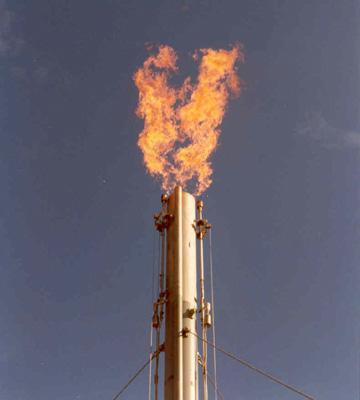
Flare Stacks
Flares burn combustible gas or vapor to produce harmless products that can be released into the atmosphere. Liquid droplets can be burned in a flare stack as well, but the droplet size must be limited to avoid sending burning waste out of the stack. This would likely result in burning waste falling onto nearby structures and equipment, potentially injuring anyone nearby.
Quench Pools
Quench pools are direct contact condensers that aid in the treatment of both liquid and vapor relieved from a system. They function by sending a stream of the relieved effluent into a pool that cools the effluent while condensing any vapors. They can also neutralize a reaction that may be taking place. Quench pools are unvented or vented depending on the effluent entering the pool. This means that they can be closed or can have noncondensable gases sent to another piece of treatment equipment or released into the atmosphere.
Case Studies
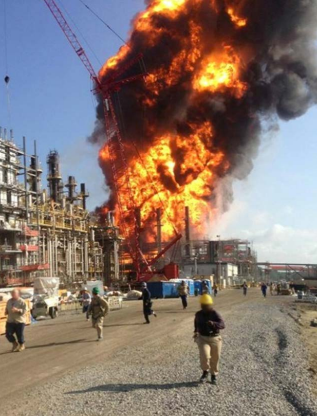
Case Study 1: 2013 Williams Olefins Equipment Rupture, Fire, and Explosion
In 2013, a reboiler in a Williams Olefins plant ruptured, causing an explosion and subsequent fire that lasted for three and a half hours as a result of the ignition of propane and propylene process fluid. In this incident, two employees were killed and an additional 167 injuries were reported.
In this plant, they had two functional reboilers that they switched between to maintain continuous operation. The reboilers functioned by sending 185°F water into the tank of the reboiler and partially vaporizing the propane within the shell of the reboiler. When one of the reboilers was not functioning properly, the operations supervisor opened the quench water valves on the offline reboiler to begin switching to the other reboiler. Due to a mistakenly opened valve or equipment failure, propane was already within the shell and began to expand while the exit shell valve was closed.
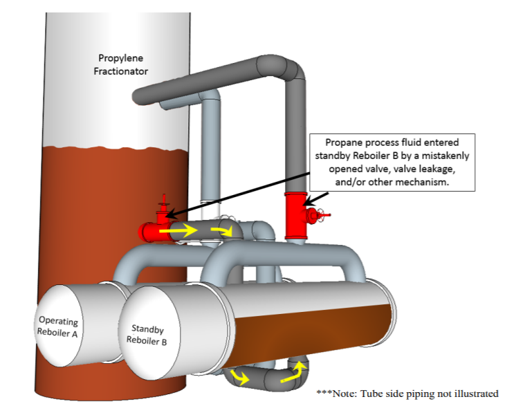
With nowhere to go, the pressure within the shell quickly increased and the reboiler shell failed. This case study demonstrates the importance of ensuring an open path to relief devices. If the relief valve had been opened prior to the quench water valves, it would not have mattered that propane was already within the shell as it would have had a route through which it could escape to relieve pressure. An additional pressure relief valve would also have helped, as it could have relieved pressure once it reached a certain point without the need for human operation.
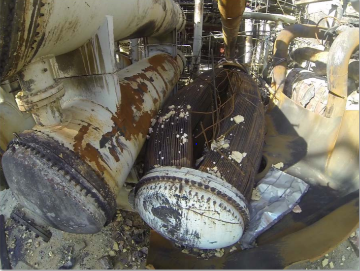
Case Study 2: 2008 Goodyear Heat Exchanger Rupture
In 2008, a heat exchanger rupture and ammonia release at a Goodyear Tire and Rubber Company plant killed one employee and injured five others. This incident happened when an isolation valve placed between the heat exchanger and relief valve was closed to replace a burst rupture disc. The next day, a block valve between the heat exchanger and a pressure control valve was closed, and steam was supplied to the process to clean out the process piping. With no opportunity to relieve the building pressure as steam was supplied, the heat exchanger ruptured, killing one worker and exposing five more to the process coolant, ammonia. The picture below was taken after the heat exchanger ruptured, showing the damage to the equipment and surrounding area.
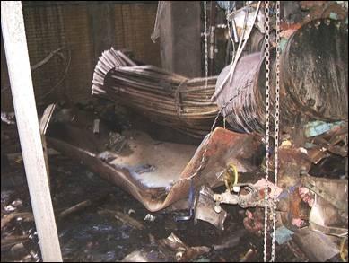
This case study demonstrates the importance of always having an open path to relief devices, even when maintenance is being performed. In this case, the proper relief equipment was in place, but when maintenance was being performed, the same level of awareness of pressure buildup was not demonstrated.
For more case studies, please visit the CSB case studies webpage and the SAFEChE website.
Acknowledgments
- Continental Disc Corporation
- Emerson Process Management
- FLAREGAS Corporation, Nanuet, NY
- Skolink Industries, Inc., Chicago, IL
- Tri-Mer Corporation, Owosso, MI
References
- Bequette, B. Wayne. Process Control Modeling, Design, and Simulation. Prentice Hall PTR, 2002. https://www.safaribooksonline.com/library/view/process-control modeling/0133536408/0133536408_ch01.html
- Bukowski, Julia, et al. “The Effects of Maintenance Actions on the PFDavg of Spring Operated Pressure Relief Valves.” ASME, Proceedings of the ASME Pressure Vessels and Piping Conference – 2014; July 20-24, 2014, Anaheim, California, USA, 2014.
- CCPS (Center for Chemical Process Safety). Guidelines for Initiating Events and Independent Protection Layers in Layer of Protection Analysis. American Institute of Chemical Engineers, John Wiley & Sons Inc., 2015. https://onlinelibrary.wiley.com/doi/pdf/10.1002/9781118948743.app5
- Cross, James, personal communication, 2016.
- Crowl, Daniel A., Louvar, Joseph F. Chemical Process Safety: Fundamentals with Applications New Jersey: Prentice-Hall P T R, 1990. Print.
- Crowl, Daniel A., and Scott A. Tipler. “Sizing Pressure-Relief Devices.” Sizing Pressure-Relief Devices. AICHE, Oct. 2013. Web. 30 Nov. 2015.
- Doyle III, Francis J., Edgar, Thomas F., Mellichamp, Duncan A., and Seborg, Dale E. Process Dynamics and Control. 3rd ed. New York: John Wiley & Sons, 2011. Print.
- Guidelines for Pressure Relief and Effluent Handling Systems. New York, NY: Institute, 1998. Web.
- Luyben, Michael L., and William L. Luyben. Essentials of Process Control. McGraw-Hill, 1997.
- Mukherjee, Siddhartha. Pressure-Relief System Design. Chemical Engineering, November 2008: 40 – 45.
- Smith, Cecil. “PID Explained for Process Engineers: Part 1 – The Basic Control Equation.” AIChE , CEP Magazine, Jan. 2016. https://www.aiche.org/resources/publications/cep/2016/january/pid-explained-process-engineers-part-1-basic-control-equation?ct
Developers
- Eric Giuffrida
- Michael Andrews
- Fritz Hyde
- Alex White
- John Novak