While no reactor can achieve zero risk of fire, explosion, or thermal runaway, many process control methods exist to control pressure, temperature, and other hazards within a reactor.
Thermal runaway is the primary risk associated with chemical reaction engineering. In exothermic reactions, the reactor temperature increases due to the heat generated by the reaction, which is balanced by the heat removed by the cooling system. In addition, the other species inside the reactor have the capacity to absorb that increase in energy, as dictated by their specific heat. This will determine the rate at which the temperature change takes place. An additional caveat is that increasing temperature will in most cases increase the rate of reaction.
Thermal runaway occurs at the temperature of no return, the temperature at which the heat generated by the reaction becomes greater than the maximum amount of heat the cooling system is capable of removing. When a thermal runaway occurs, the temperature and pressure within a vessel can increase until the point of explosion or until a reactant is exhausted. As such, the purpose of safe reactor design is to reduce the risk of thermal runaway. In addition to process controls described in the pressure control and temperature control modules, hazard evaluation techniques allow operators to determine the level of risk associated with their reactors and invest in safety measures accordingly.
The risk associated with a reactor is largely determined by the potential for the temperature and pressure controls to fail. Without pressure and temperature controls, such as vents and cooling jackets, exothermic reactions could generate heat and pressure within the reactor until the reactor bursts, which could result in an explosion and/or a fire. Designed layers of protection, such as cooling jackets, containment pots, and rupture valves can be put in place to prevent disasters.
Types of Runaway Reactions
As discussed in the case studies above, a runaway reaction occurs when the pressure and temperature of an exothermic reaction increase without sufficient control. In an exothermic reaction, the rate of heat release varies exponentially with temperature while the rate of cooling varies linearly with temperature. As such, exothermic reactors are typically designed with numerous cooling systems to prevent thermal runaway, such as ventilation. When a reactor vent is opened, vapor pressure reactions will lose heat to the atmosphere through vaporization, reducing the temperature and pressure of the reactor. Gas-phase systems, on the other hand, are composed of non-condensable gases, so their pressure would not be reduced when the reactor is opened to the atmosphere. Large vents are required to remove non-condensable gas from a gassy reactor.
Vapor Pressure Reactions
A vapor pressure system is one in which no permanent gas products are generated. The contents of a vapor pressure reactor will boil (or vaporize) before they decompose into non-condensable gases, so no non-condensable gases will form. The pressure of the reactor is determined solely by the vapor pressure of the contents of the reactor. In these situations, a calorimeter measures the rate of temperature increase between the set pressure and the maximum pressure determined by the operator. These reactors typically require smaller vents because the contents of the reactor can be condensed. Because vapor pressure is dependent on temperature, reducing the pressure of the reactor also reduces its temperature. The size of the vent is dependent upon the rate of temperature rise at standard operating pressure.
Gassy Reactions
A gassy system is one in which the only source of pressure increase is the generation of non-condensable gases. The gas generated in these reactions comes from the decomposition of the reactor contents. The pressure of the reactor is equal to the pressure of the generated gases. Calorimeters determine the maximum rate of pressure increase from the gases generated, and vents are sized to reduce the pressure of the reactor by at least that amount. Unlike in vapor pressure reactions, reducing the pressure of a gassy reaction does not reduce its temperature. Additional controls are necessary to reduce the temperature of a gassy system.
Hybrid Reactions
Hybrid reactions have significant vapor pressure and also produce non-condensable gases. In these reactors, some reactor contents decompose before they boil and others do not. The total pressure in the reactor is the sum of the partial pressure of the gaseous product and the vapor pressure. Ventilation can reduce both pressure and temperature in a hybrid system; the vent size is determined by the flashpoint of the reactor contents.
Hazard Evaluation Techniques
Hazard evaluation techniques set the degree of risk of thermal runaway associated with a chemical reaction to determine parameters (pressure, temperature, the quantity of reactants, etc.) for the safe operation of a reactor. Individual reactants and products can be screened for hazards using a Safety Data Sheet or SDS (previously known as Material Safety Data Sheet or MSDS). An SDS will contain hazard identification, first aid guidelines, fire prevention and fighting measures, accidental release measures, toxicological information, and other safety data. For more information on SDSs, see the Process Safety Fundamentals module.
Preventing Thermal Runaways
Most industrial reactors have layers of protection or multiple safety measures in place should the temperature of the reactor rise beyond the operating target. A process control system monitors the temperature of a reaction and either manually or automatically initiates temperature control mechanisms built into a rector. Common layers of protection for reactors include bypass valves, quench valves, and containment pots.
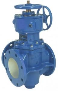
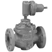
Bypass valves allow for additional water to be drawn from a cooling fluid reservoir to the cooling jacket that typically surrounds a reactor. Once an exothermic reaction reaches the desired operating temperature, cooling fluid is drawn from the reservoir to the jacket to maintain the temperature at the target. If the temperature increases past the operating target, additional cooling fluid will be required to reduce the temperature to the desired value. A common type of bypass valve is the plug valve, pictured below.
In case additional cooling water is not sufficient to prevent thermal runaway, quench valves can be included to transfer the reaction components into a cooling tank. Quench valves are often installed in the base of a reactor and open when the temperature sensor identifies that less intense cooling mechanisms have failed. When a quench valve opens, the contents of the reactor are emptied into a cold water tank. This eliminates the risk of thermal runaway. Unlike coolant bypass valves, quench valves force the reactor to shut down.
If the quench valves also fail, containment pots are often the last line of defense from thermal runaway. Containment pots attempt to contain the contents of an explosive reactor and prevent damage to the surroundings. These structures, often made of concrete, surround a reactor vessel and are designed to contain the results of an explosive reaction.
Determining Heats of Reaction
The heat evolved or is absorbed in a reaction and the heat capacity of individual reactants can be measured using a calorimeter. Reaction calorimeters consist of thermocouples and reference materials with known heat capacity and are used to measure the change in temperature of the reference material over the course of a reaction, allowing the operator to determine the heat evolved during the reaction. Most calorimeters use the “heat-wait-search” method of sensing temperature changes. In this method, the reactor is heated by a small amount than allowed to reach a steady-state. If heat is evolved, then the temperature will increase. This temperature increase is referred to as an exotherm and could result in a thermal runaway. Common types of reaction calorimeters include accelerating rate calorimeters (ARC), automatic pressure tracking adiabatic calorimeter (APTAC), vent sizing packages (VSP), and advanced reactor safety screening tool (ARSST) calorimeters.
Accelerating rate calorimeters (ARCs) measure the temperature and pressure of a reaction sample under conditions of thermal runaway. A small sample of a reactor’s components is placed in a small heated metal sphere called a bomb. The temperature of the surroundings is then elevated to the temperature of the sphere. Thermocouples on the inside and outside of the sphere measure the temperature of the calorimeter and the heater increases the temperature of the surroundings as the temperature of the reactor increases. ARCs are capable of detecting temperature changes of as little as 0.02 ° C per minute. The time required to reach the maximum rate of temperature increase is the time at which the reaction begins to run away; the temperature at this time is referred to as the temperature of no return.
Automatic pressure tracking adiabatic calorimeters (APTACs) are also used to characterize exothermic reactions. An APTAC consists of a spherical cell in which the reaction contents are placed, a powerful heater to control the temperature outside the cell, and a nitrogen supply to vary the pressure surrounding the cell. The containment cell in an APTAC can be opened to the environment to study the effects of pressure relief systems. APTACs measure the pressure and temperature within the reaction cell and can detect temperature changes of 0.04°C per minute.
Vent sizing package calorimeters (VSPs) are comprised of a test cell enclosed in a large containment vessel. The containment vessel regulates its own pressure so the test cell does not burst; this makes it possible for the test cell to have a thin wall that minimizes heat loss to the surroundings. VSP calorimeters typically can detect temperature changes rates of 0.05°C per minute. A VSP can reach final temperatures of up to 400°C, often to the point where reactants begin to decompose. This feature allows VSP calorimeters to be used to determine the temperature at which the contents of the test cell begin to decompose.
Advanced reactor safety screening tool (ARSST) calorimeters consist of a small glass test cell, thermocouples, a pressure transducer, and a larger containment vessel that can be pressurized to test the heat of reaction under various pressures. The containment vessel also encapsulates the test cell in case of leakage or explosion. The ARSST is more adiabatic than most other calorimeters and can detect temperature changes of 0.1°C per minute. The thermocouple measures the temperature inside the test cell, and the pressure transducer can measure pressures of nearly 1000 psig. The containment vessel is connected to an inert gas supply to prevent explosions.
Temperature Measuring Devices
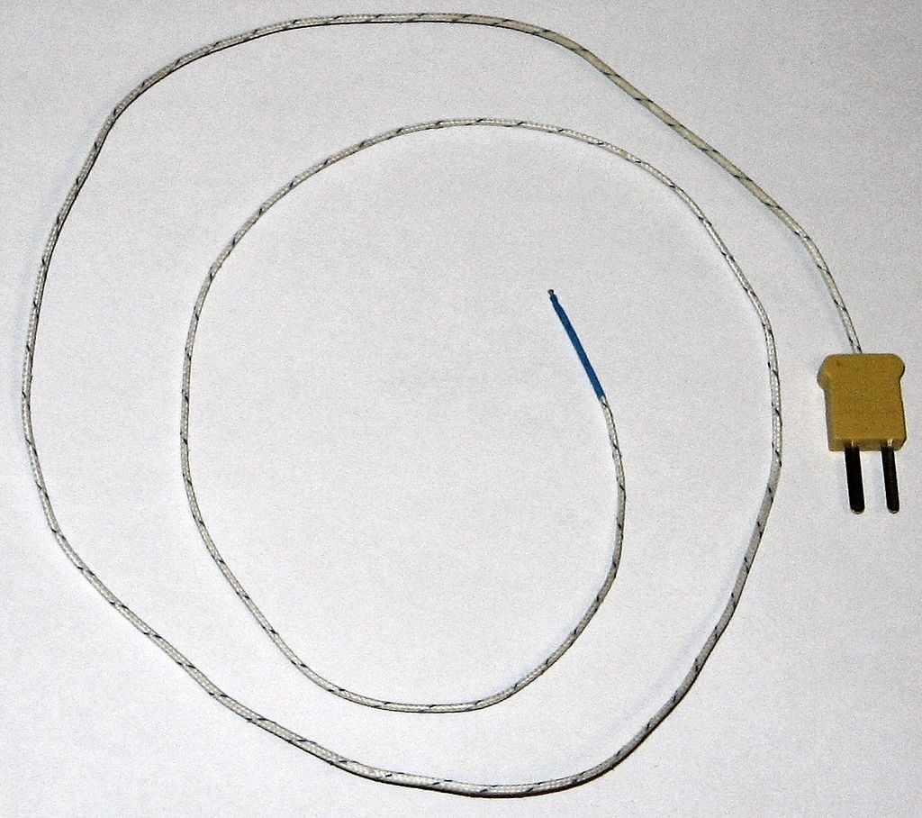
Thermometers are the most common type of temperature measurement equipment and are often used in academic laboratory settings. Thermometers are composed of an expansion chamber, scale, stem, and bulb. Thermocouples are the most commonly used temperature measuring device in the chemical processes industry, and function by converting a measured voltage into a temperature value. Thermocouples, such as the one shown below, record the difference between two dissimilar metals and a reference junction.
Thermistors measure temperature by recording electrical resistance changes that are caused by temperature differences. These devices are made up of metal oxides with epoxy coatings. Thermistors have applications that include monitoring heat loss in pipes. Resistance temperature detectors, most commonly referred to as RTDs, measure a change in resistance due to temperature change. RTDs are composed of pure metals. They are very accurate and have a fast response time. These devices are very common in the chemical process industry and have applications in equipment such as distillation columns and reactors. Pyrometers measure the temperature at a specific point by measuring the emitted power density from an object. Infrared pyrometers focus infrared light from a lens to a detector, while optical pyrometers use filaments to match filament color to object color in order to determine the temperature of an object. Pyrometers are often used for measuring the temperature of steam traps, semiconductors, and race car tires. For more information on the several types of temperature measurement devices mentioned above, please see the temperature measurement section.
Pressure Relief Valves
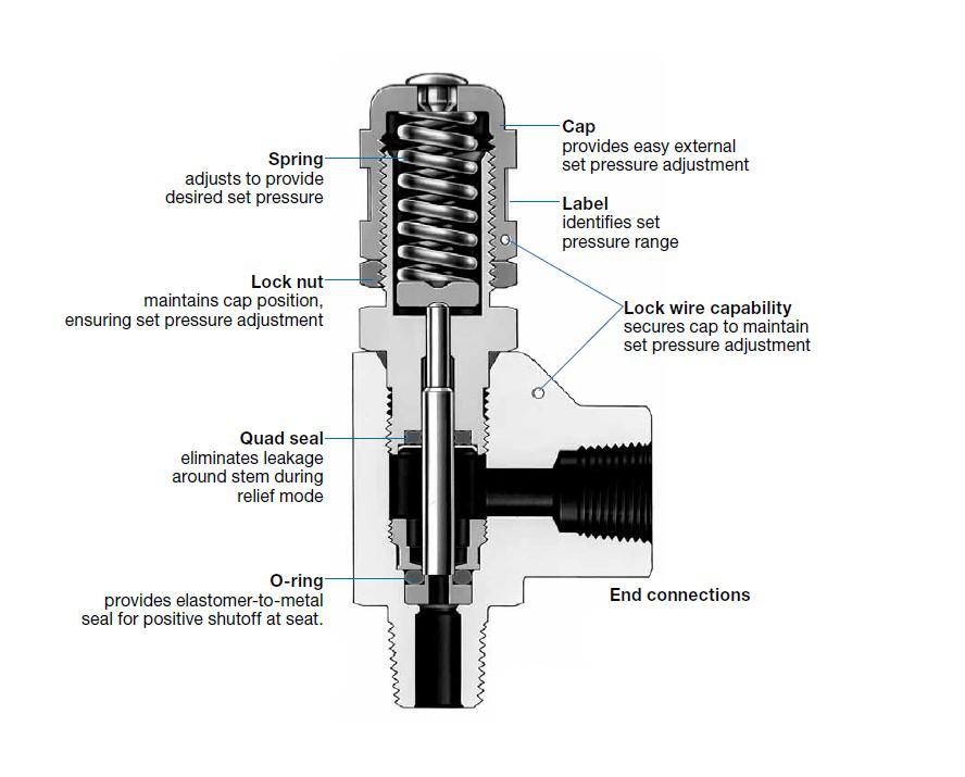
Pressure relief valves (PRVs) prevent the pressure inside a reactor from increasing beyond an acceptable limit by allowing gas or liquid to escape a vessel. PRVs default to a closed position and open once a (typically automatic) sensor senses an unacceptably high pressure. When a PRV opens, reactor contents flow out of the reactor to either a combustion area or the open air. With fewer high-pressure contents in the reactor, the pressure within the reactor will decrease to within the acceptable limits. The two most common types of pressure relief valves are direct-loaded and pilot-operated. The figure below is of a direct-loaded PRV with individual components labeled.
Direct-Loaded Pressure Relief Valves
Direct-loaded PRVs consists of a spring-loaded disc. The fluid within the reactor exerts a force on the disc, which is counterbalanced by the spring holding the disc in place. When the pressure exerted on the disc by the fluid within the system exceeds the maximum force the spring is capable of exerting on the disc, the valve opens and the fluid escapes the vessel through a duct. An operator can adjust the pressure limit by choosing the amount of force with which to load the spring.
Pilot-Operated Pressure Relief Valves
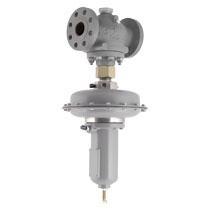
Pilot-Operated PRVs consists of a valve, a piston, and a dome affixed above the piston. The fluid exerts a force on both the dome and piston sides of the valve, but the dome has a larger surface area than the piston, so a greater force is exerted on the dome. This holds the piston in place. When a greater force is exerted on the valve than acceptable, the pressure on the dome is released, and the fluid pushes the piston out of the way so the fluid can escape from the vessel through a duct. When the pressure falls below the acceptable upper limit, the piston will fall back into place and re-seal the vessel.
The pictures below compare a direct-operated PRV, on the left, to a pilot-operated PRV, shown on the right.
Inherently Safer Reactor Design
Reactors can be generally sorted into one of two categories: Continuous and batch reactors. A continuous reactor has input streams and output streams, and the materials react as they pass through the reactor. A batch reactor is charged with reactants before being activated, then deactivated once the reaction takes place. The figure on the left is of a batch reactor with a stirrer on top, while the figure on the right is a continuous reactor with inlet and outlet streams.
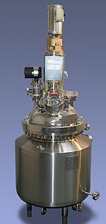
Often in industry, unreacted materials are the most hazardous. Batch reactors handle larger quantities of raw materials than continuous reactors do, so continuous reactors are inherently safer than batch reactors. Batch reactors can occasionally be operated under semi-batch conditions, where one reactant is continuously fed into a reactor charged with a different reactant. This is safer than traditional batch operation because fewer unreacted raw materials sit in the reactor, and heat can be removed as quickly as reactants are added. Furthermore, reactors are most vulnerable to accidents during startup and shutdown, and batch reactors are typically started and stopped more often than continuous reactors.
Liquid-phase reactors typically contain more material at higher internal energy than vapor phase reactors. Therefore, operating reactors in the vapor phase are inherently safer than operating in the liquid phase.
Two common reactor designs are tubular and tank reactors. In a tubular, or plug flow reactor (PFR), materials are pumped through a pipe or tube through the reactor and the reagents react to form a product as they travel down the reactor, as shown in the video below, and described in the PFR module:
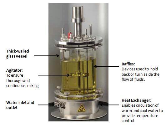
In a tank reactor, the reagents are fed into a large tank and an impeller causes the reagents to mix and react to form a product. Tubular and continuously stirred tank reactors or CSTRs can be operated in batch or continuous mode, as shown in the reactors section. However, tubular reactors are inherently safer than tank reactors because they have no moving parts and fewer joints and connections at which leaks can form. Tank reactors, on the other hand, have an impeller and numerous inlet and outlet flow streams, all of which are potential points of failure.
Case Studies
Case Study 1: 2007 T2 Laboratories Explosion and Fire
In 2007, an explosion occurred in a 2,500-gallon batch reactor producing methylcyclopentadienyl manganese tricarbonyl MCMT, a gasoline additive, at T2 Laboratories in Jacksonville, FL. The resulting explosion killed four T2 workers and injured thirty-two additional individuals.
The explosion occurred due to an inadequate cooling system regulating the temperature of MCMT production, an exothermic process. The process used in MCMT production involved a batch reactor with a water cooling jacket, in which water would be pumped into a surrounding vessel and evaporated off in order to cool the MCMT reaction.
The process had experienced several thermal regulation issues before this event, mainly because the operation was upscaled from a test reactor several orders of magnitude smaller. Those implementing the process neglected that the cooling of the reactor would be approximately proportional to the surface area (length squared) of the cooling jacket, while the rate of exotherm would increase with the volume of the reaction (length cubed). In essence, the reactor was reliant on a high degree of manual control because it was not operating at a steady state.
Additionally, the cooling water had no reserve tanks or backup valves, so a single failure of the waterline was sufficient to cause a thermal runaway. A rupture disk was set to initialize the pressure relief system once the reactor pressure passed 400 psig, but the reaction was already uncontrollable before the system reached this pressure. The runaway reaction increased the pressure in the reactor by an estimated 32,000 psi per minute, causing an immediate tank rupture and subsequent explosion. Had T2 installed redundancies within its process control system the disaster could have been prevented. Additionally, testing the reaction in an ARSST ( Advanced Reactive System Screening Tool) calorimeter would have informed the plant managers that as temperature and pressure increased, a second, highly exothermic side reaction occurs.
Case Study 2: 1960 Monsanto Chemical Company
An explosion occurred at a plant owned by Monsanto Chemical Company, in a batch reactor for the production of nitroaniline, a precursor for industrial dyes. This reactor typically operated at 175°C and 500 psi. The reactor was surrounded by a cooling jacket that supplied water at an ambient temperature of 25 ° C; the flow rate of the water could be adjusted to respond to disturbances in the reactor temperature and maintain the reactor at 175°C. Typically, only one-third of the reactor was charged with reactants; however, management suggested that the operators triple production and fully charge the reactor. Engineers calculated the expected heat generated from tripled production and the capability of their cooling system and found that at tripled production, heat removed still exceeded heat generated. Therefore, this reaction was deemed controllable and the plant tripled production.
At some point in the process, though, the cooling system went offline; it took engineers approximately ten minutes to restore power to the cooling system. During those ten minutes, zero heat was recovered, so the temperature in the reactor began to rise. The temperature in the reactor had risen to 195°C when the cooling water was reactivated. With the reactant flow rate tripled and the reactor operating at 195°C, the heat generated by the reaction exceeded the maximum heat removable by the cooling water. The reaction crossed the point of no return and the reactor temperature increased until rupture occurred. The reactor was equipped with an emergency pressure relief valve designed to vaporize all water within the system. This would have removed far more than enough heat from the reactor to prevent thermal runaway. However, the pressure relief valve also failed to function and the reactor proceeded to explode approximately one hour after the cooling system failed. The three events that caused the explosion were the tripling of production, the failure of the cooling system, and the failure of the relief valve. Had any of those events not occurred, the explosion would have been prevented.
Case Study 3: 1977 Air Products Nitrous Oxide Explosion
An explosion occurred at an Air Products nitrous oxide plant in which ammonium nitrate, a chemical used to produce nitrous oxide, was heated to the point of thermal runaway. A solution of roughly 80% ammonium nitrate and 20% water was typically fed into a reactor, which decomposed to form a nitrous oxide and steam. The ammonium nitrate mixture was fed to the reactor at 200 °F, while the reactor itself operated at 500 °F. The operators noticed that their system to control pressure was failing, so they decided to shut off the feed to the reactor. The reasoning behind this decision was to prevent any more ammonium nitrate from entering the reactor because ammonium nitrate is flammable at high temperatures. Within five minutes, the reactor exploded, killing four men and injuring two more. While the loss of pressure control was problematic, the root cause of the explosion was the halting of the feed stream. Because the feed stream was at a lower temperature than the reactor, the feed stream also served as a cooling mechanism. By shutting off a stream that was colder than the reactor, the temperature in the reactor began to rise and quickly reached thermal runaway. The decision to reduce the ammonium nitrate content in the reactor was reasonable; the method of doing so was what caused the explosion. The operators should have gradually phased out the ammonium nitrate from the feed stream and replaced it with an equivalent volume of water so that the feed stream could remove the same amount of heat until pressure control could be restored. Had the operators not halted the feed stream to the reactor, the explosion would not have occurred.
For more case studies, please visit the CSB case studies webpage and the Reactions module on the SAFEChE website.
Acknowledgments
- DeZurik, Inc., Sartell, MN
- Emerson Process Management, Chanhassen, MN
- New Brunswick Scientific, Edison, NJ
- Pfaudler Inc., Rochester, NY
- The Swagelok Company
- Wikimedia Commons
References
- API STD 521, Pressure-relieving and Depressuring Systems, Fifth Edition, January 2007 (Addendum May 2008).
- Burelback, J.P. (2000, October 4). ADVANCED REACTIVE SYSTEM SCREENING TOOL (ARSST). Retrieved January 17, 2017, https://www.fauske.com/sites/default/files/AdvancedReactiveSystemScreeningTool_ARSST_NATAS.pdf
- Coker, A. K. (2001). Modeling of Chemical Kinetics and Reactor Design (2nd ed.). Gulf Professional Publishing.
- Crowl, Daniel A., and Joseph F. Louvar. Chemical Process Safety: Fundamentals with Applications. 3rd ed. New Jersey: Prentice-Hall, 2011. Print.
- Fogler, H.S. (2016). Elements of Chemical Reaction Engineering (5th ed.). Boston: Prentice-Hall.
- H. Scott Fogler, personal communication, 2016
- Investigators sift debris from blast in quest of cause. (1977, August 3). The Morning News, p. 3. Retrieved February 13, 2017, from https://www.newspapers.com/newspage/157563853/
Developers
- Patrick Dillon
- Austin Potter