
Temperature is the measure of the average internal energy possessed by the molecules of a substance. There are four popular unit systems for temperature.
| Temperature Unit | Boiling pt. of water | Freezing pt. of water | Absolute zero |
|---|---|---|---|
| Kelvin (K) | 373 | 273 | 0 |
| Celsius (°C) | 100 | 0 | -273 |
| Fahrenheit (°F) | 212 | 32 | -460 |
| Rankine (R) | 672 | 492 | 0 |
Conversions
- T(K) = T(°C) + 273
- T(°F) = 1.8*T(°C) + 32
- T(°C) = (T(°F) – 32)/1.8
- T(R) = T(°F) + 460
- T(R) = 1.8*T(K)
Temperature is typically measured using one of the four scales shown above, along with the conversion equations.
Because it is difficult to measure molecular activity directly, temperature is determined by measuring a physical property that is dependent on temperature in a known manner.
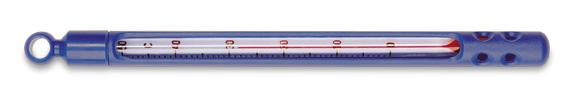
Thermometer
A thermometer is easy to use in the home and in the laboratory.
General Information
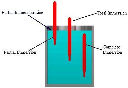
Three types of liquid-filled thermometers are available, depending on how much of it will be immersed in the medium.
| Name | Immersion depth |
|---|---|
| Partial Immersion | Only part of the thermometer is exposed to the medium under study, while the rest is exposed to air. |
| Total Immersion | The thermometer is immersed in the medium up to the level of the thermometer fluid. |
| Complete Immersion | The entire thermometer is exposed to the medium being measured. |
Equipment Design
Changes in temperature result in a change in the density of a liquid. In glass thermometers, this density change results in a change in the height of the internal liquid column. This fluctuation is measured along the stem of the thermometer.
Alcohol or mercury are often used as the thermometer fluid because they expand in a predictable manner.
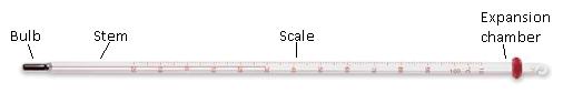
- Expansion Chamber – An enlargement of the capillary bore at the top of the thermometer to prevent buildup of excessive pressures in gas-filled thermometers.
- Scale – Scale is graduated in degrees, fractions or multiples of degrees.
- Stem – The stem is the glass capillary tube in which the liquid is housed. The liquid level fluctuates with temperature changes.
- Bulb – Reservoir for the thermometer fluid.
Usage Examples
Thermometers are very popular in the research industry and in schools. Here a thermometer is being used to measure the temperature of a liquid.
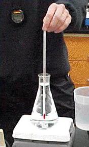
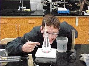
(Copyright Chemical Engineering Department, University of Michigan, Ann Arbor, MI)
Advantages
- Easy to use and understand
- Inexpensive
Disadvantages
- Some contain mercury, a corrosive and toxic metal
- Measures only a small range of temperatures
- Slow response time
Thermocouple
Thermocouples, also called thermoelectric couples, are the most common type of temperature sensors in the chemical process industry. They use voltage to measure differences in temperature.
General Information
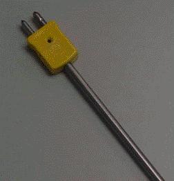
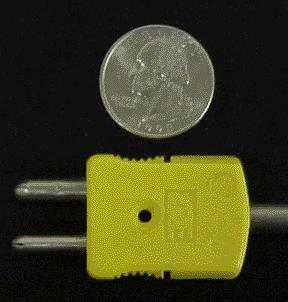
Thermocouples can be very small, with wire diameters as little as 0.005 inches. They work by measuring the voltage difference between the junction of two dissimilar metals and a reference junction. The reference junction is held at a constant temperature to provide a comparison temperature when evaluating the voltage difference.
There are three types of junctions available.
| Exposed | Ungrounded | Grounded |
|---|---|---|
| Junction extends beyond insulation. Best for noncorrosive environment where fast response time is desired. | Junction is physically insulated from the sheath. Best for corrosive environments where thermocouple should be electronically insulated. | Junction is welded to the sheath. Best for corrosive gas and liquid temperatures, and for high pressure. Has a faster response time than ungrounded junctions. |
 |  |  |
(Copyright Marlin Manufacturing Corporation, Cleveland, OH)
Equipment Design
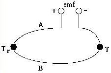
A thermocouple is composed of two wires of different metals , A and B, connected at two junctions that are at different temperatures, T and T r , shown below. The temperature difference between the two junctions generates a voltage difference which is measured by a potentiometer. The choice in metal pairs is dependence on their electrical properties, stability, and reproducibility. Some common combinations are chromel and alumel, iron and constantan, copper and constantan, and platinum and platinum-rhodium.
In this thermocouple configuration below the metal wires (A and B) are referenced to copper leads in an ice bath, to remove errors due to temperature differences at the junction. The copper leads are connected to the potentiometer, which measures the voltage difference between the measured temperature T and the reference temperature T r .
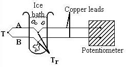
Many thermocouples can be combined in series to measure values of T at several locations or to provide a larger temperature measurement signal. To minimize errors in the reference temperature T r , thus ensuring accurate temperature measurements, the reference junction temperature must be known and constant. This is accomplished using an ice bath, shown above, or an electric ice point.

An electric ice point consists of several reference wells into which the reference junctions are inserted. The wells are extended into a sealed chamber containing water. The outer walls of the chamber are cooled, freezing the water in the cell. The freezing water causes an increase in volume which is sensed by a bellows . The bellows operates a microswitch that turns off the cooling element, thawing the water. The alternating freezing and thawing of the water in the cell accurately maintains an environment of 0°C around the reference wells.
Usage Examples
Depending upon the metal combination, thermocouples have different temperature ranges and environmental constraints (e.g. air or vacuum).
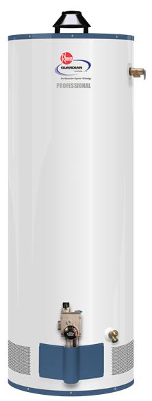
Thermocouples are sometimes attached to pieces of equipment to monitor temperature during operation. Thermocouples are often used in gas-fed heating appliances that use a pilot light to ignite the main gas burner, like the water heater pictured below. If the pilot light goes out, then the thermocouple will cool down and the gas valve will be closed.
Advantages
- Adaptable for installation in small assemblies and confined, remote, or virtually inaccessible areas.
- Accurate within 0.4% over a wide range of temperatures ( 0ºC to several thousand degrees Celsius)
- Relatively inexpensive compared to RTDs
Disadvantages
- Electromagnetic interference due to generation of voltages in lead wires.
- Additional materials (e.g. if the thermocouple requires mechanical support when attached to a piece of equipment) must be compatible with the thermocouple to avoid error due to contamination.
- Performance deteriorates under many application conditions.
- Interdiffusion between metals may occur.
- Impurities in ice baths could change the reference temperature.
- Need frequent recalibration
Thermistor
General Information
Thermistors are made of materials whose electrical resistance changes with temperature. They are very sensitive and accuracy is usually limited only by the readout device.
Thermistors are manufactured from oxides of nickel, iron, cobalt, copper, titanium and other metals and are covered by an epoxy.
Equipment Design
Thermistors also come in a variety of shapes and sizes depending on the application.
Thermistors can be used in vapor or gas environments, as well as on flat surfaces.
Usage Examples
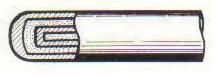
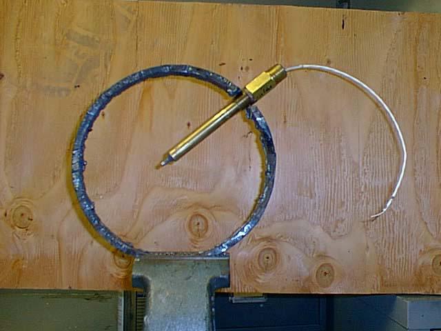
Thermistors have many applications. For example, two thermistors placed on a pipe at different locations can be used to monitor heat loss. The picture below shows a cross-sectional view of a pipe with a thermistor.
In addition, a thermistor and a variable resistor together can be used for temperature control when a heater or cooler is connected to the circuit.
Advantages
- Very sensitive to temperature changes
- Faster than thermocouples
Disadvantages
- Operating temperature range of 0 to 600 °F limits use
Resistance Temperature Detector (RTD)
General Information
Resistance temperature detectors are the second most widely used temperature sensor device in the chemical process industry behind thermocouples. Like thermistors, RTDs work by measuring a change in resistance with temperature.
Unlike thermistors, RTD’s are made of pure metals, such as platinum, or copper.
Usage Examples
RTD’s have many uses, but are most often seen when a high degree of accuracy or a fast response time is needed. Distillation columns, reactors and heat transfer units usually have RTD temperature sensors, because a few degrees of inaccuracy could result in wasted steam, extra feedstock or a rejected product.
Advantages
- 0.12% accuracy is standard
- More than twice as accurate as thermocouples
- Faster than thermocouples
Disadvantages
- Operating temperature range of 0 to
600ºC - More expensive than thermocouples
Pyrometer
A pyrometer is a device that measures the temperature of an object at one point by measuring the total power density emitted. Pyrometer designs range from handheld to fiber-optic to analog devices.
General Information
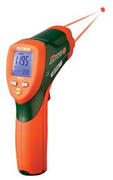
The two main types of pyrometers are infrared, such as the one shown here, and optical. Pyrometers work on the principle of Planck’s Law that relates the temperature of a black body to the wavelength of emitted radiation. Because Planck’s Law is for a black body, IR pyrometers must compensate for the difference in emissivity, which is the measurement of a material’s ability to absorb or reflect energy.
Equipment Design
Infrared Pyrometers
These pyrometers use infrared light to measure the temperature of objects. The most basic design consists of a lens and a detector. The lens focuses the infrared energy onto the detector, which converts the energy into an electrical signal that is displayed as a temperature reading after compensating for the ambient temperature and emissivity of the material. For single wavelength pyrometers the object being measured must completely fill the field of view of the instrument. This ensures that no objects of differing temperature are measured.
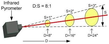
The distance-to-spot ratio (D:S) or “field of view” relates the “spot,” or size of the measurement region, to the distance to the target, which helps determine how far from the target the pyrometer should be placed. The image below shows an example of a pyrometer with a D:S value of 8:1.
Ratio Infrared Pyrometers
Ratio pyrometers, also called dual-wavelength or two-color, are less sensitive to variations in the target area. These devices measure the radiation in two different wavelength regions with two different detectors, then determine the temperature from the ratio of these two signals. Ratio pyrometers are calibrated for the signal ratio against temperature, while single-wavelength devices are calibrated for signal level to temperature. Most ratio pyrometers require the user to adjust the emissivity ratio between the two wavelengths. If the correct ratio is used, very accurate temperature measurements are possible. Ratio thermometers are also resistant to obstructions in the field of view or to targets that don’t completely fill the field of view, since obstructions will decrease the signal at each wavelength equally and the same ratio will be obtained.
Shown here are examples of some cases where ratio pyrometers will obtain accurate measurements when single wavelength devices will not.

Optical Pyrometers
Optical pyrometers are used to measure the temperature of small, hot incandescent materials such as tungsten. To measure temperature using an optical pyrometer, an operator manually judges when the color of a filament matches that of the object . The light from the source is filtered to select a narrow wavelength band in the red region of the visible spectrum. Other filters reduce the intensity of the light to increase the temperature range capability of one instrument.
Because the wavelength is restricted to the red region, the minimum temperature that can be measured is about 700°C, limiting the use of optical pyrometers to specialty applications.
Usage Examples
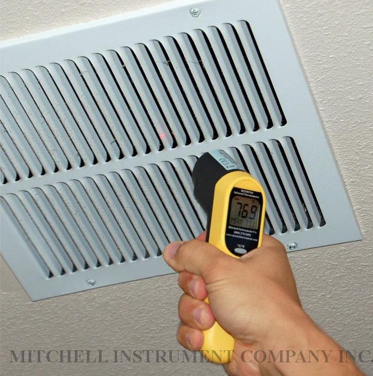
Pyrometers are most useful for measuring the temperature of objects that are at high temperature, moving, surrounded by an electromagnetic field, or in a controlled environment. They are commonly used for racecar tires, pottery kilns, steel mills, steam traps, and semiconductors. The picture below shows an infrared thermometer being used to measure the temperature inside a vent.
Advantages
- Hand-held and easy to use
- Very accurate and precise
- IR can easily be integrated into a process for constant temperature monitoring
- Quick (1-2 second) response time
- No contact with target object is necessary
- Excellent for high temperature and moving objects
Disadvantages
- Expensive
- Optical pyrometers require an operator for use
- Almost impossible to check error of measurement
- Accuracy easily affected by dust, smoke, and background radiation
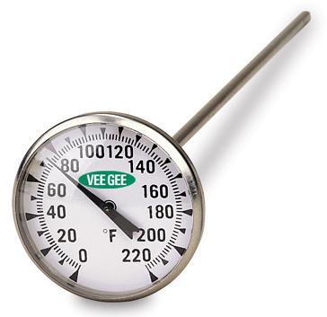
Bi-Metal Thermometer
General Information
A helix in the tip of the stem is made of two metals pressed together. When a temperature change occurs, one metal expands a little more than the other, causing the connected needle to rotate, indicating a change in temperature.
Usage Examples
Bi-metal thermometers like the one pictured below can be used in refrigerators and warmers. Other applications include measurement of ground temperature or food temperature.

Acknowledgements
- Chemical Engineering Department, University of Michigan, Ann Arbor, MI
- Emerson Process Management
- ENERGY STAR, Washington, DC
- Extech Instruments Corporation, Nashua, NH
- Lawrence Berkeley National Laboratory
- Marlin Manufacturing Corporation, Cleveland, OH
- Mitchell Instrument Company Inc., San Marcos, CA
- Rheem Manufacturing Company, Atlanta, GA
- VEE GEE Scientific, Inc., Kirkland, WA
References
- Benedict, Robert P. Fundamentals of Temperature, Pressure, and Flow Measurements . New York: John Wiley & Sons, 1984: 7-12, 45-51, 53-71, 224-247. Print.
- Bentley, Robin E. 1998. Handbook of Temperature Measurement. New York: Springer. Print.
- Kinzie, P.A. Thermocouple Temperature Measurement . New York: John Wiley & Sons, 1973. Print.
- Nguyen, Khoi. “Applying CPI Temperature Sensors.” Chemical Engineering . 9(2010): 28-31.
- Omega Complete Temperature Measurement Handbook and Encyclopedia , Vol. 28. USA: Omega Engineering. Inc., 1992. Print.
- Omega Complete Temperature Measurement Handbook and Encyclopedia , Vol. 29. USA: Omega Engineering. Inc., 1995. Print.
- Perry, Robert H., and Don W. Green. Perry’s Chemical Engineers’ Handbook , 7th ed. New York: McGraw Hill, 1997: 8-45 – 8-46. Print.
- Pollock, Daniel D. Thermocouples: Theory and Practice . Boca Raton: CRC Press, 1991. Print.
- Quinn, T.J. Temperature . London: Academic Press, 1983: 220-223, 369-375. Print.
- Sax, Irene. “Homekeeping.” Martha Stewart Living , June 1996: 74. Print.
- Young, Alan. 2002. “IR Thermometry Finds CPI Niches”. Chemical Engineering 2: 56-60. Print.
Developers
- Sam Catalano
- Brad Lintner
- Blia Kue
- Melissa Schlosser
- Chris Seadeek
- Dave Carpenter
- Kelsey Kaplan
- Andrea Roberts
- Henry Chen