Liquid-liquid extraction has only become popular as a separations technique in the past thirty years. In this time, liquid-liquid extractors have become the separation equipment of choice for selected processes.
LLE Theory
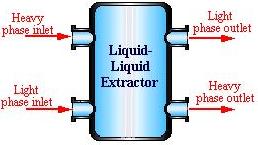
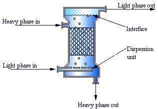
The primary inlet and outlet streams of a typical liquid-liquid extractor are shown here.
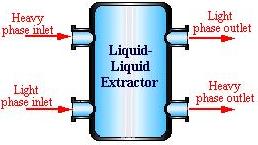
- Heavy Phase Inlet: The higher density, or heavy, the phase will fall to the bottom of the extractor. Depending on the design of the extractor it could be the dispersed phase or the continuous phase. Likewise, it could be the solute carrier or the solvent.
- Light Phase Inlet: With a lower density, the light phase will rise to the top of the extractor. This phase will have the opposite characteristic of the heavy phase in terms of dispersion vs continuous and solvent vs solute carrier.
- Light Phase Outlet: The light phase exits out the top of the extractor. Whether it had started out as a dispersed or continuous phase, it is now a continuous phase. If it was carrying the solute, it is now solute-free. If it was the solvent, it carries the solute out of the column with it.
- Heavy Phase Outlet: The heavy phase exits out the bottom of the extractor. Whether it had started out as a dispersed or continuous phase, it exists as a continuous phase. If it was carrying the solute, it is now solute-free. If it was the solvent, it carries the solute out of the column with it.
The key elements to successful LLE are solvent selection and effective mass transfer. The solvent needs to be able to extract the desired solute(s) from the feed stream, be immiscible with the other components of the feed stream, and have high recoverability. Recoverability is the ability of the solvent to be separated from the solutes after the extraction process is complete. This will greatly reduce operations costs because the solvent is usually quite expensive. Distillation is a common method of recovering the solvent.
Droplet formation is the most common method of mass transfer. The droplets are formed in either the heavy phase or the light phase so as to maximize surface area and solvent contact. Often LLE processes include a dispersion-coalescence cycle. Dispersion is the breaking up of the intact phase of liquid into the droplets necessary for mass transfer. Coalescence is the coming together of the droplets into one mass and the cycle is incorporated through a series of multiple dispersion and coalescence stages to enhance mass transfer. The picture below shows the dispersion of droplets that occurs in a liquid-liquid extraction column.
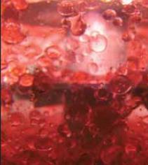
(Copyright Schulz+Partner GmbH, Teningen)
Basic Designs
Mixer-Settlers
Mixer-settlers are simple stagewise liquid-liquid extractors. As the name suggests there are two stages involved; mixing and settling.
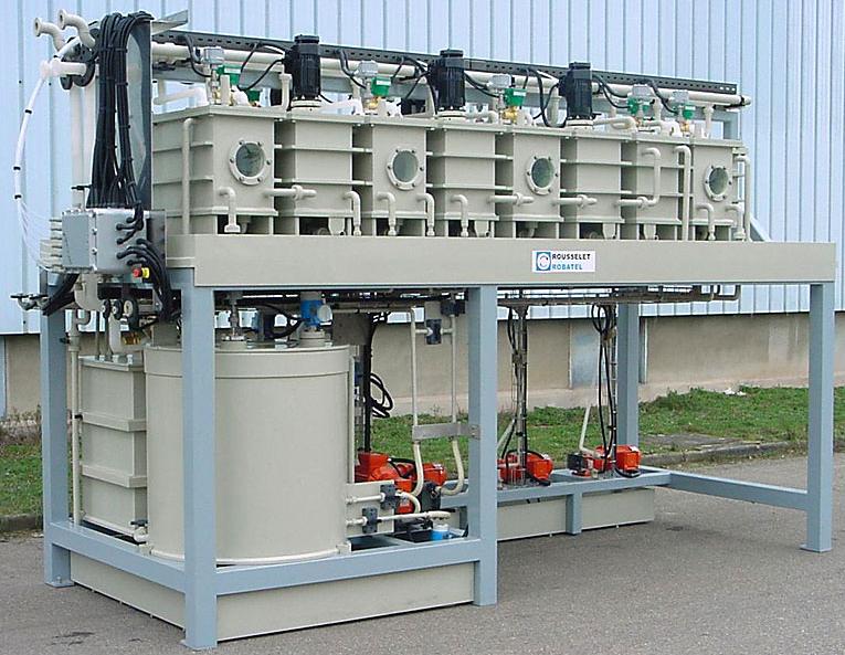
General Information
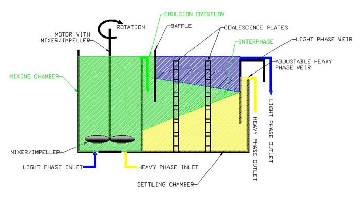
Mixer-settler liquid-liquid extractors have two stages. In the mixing stage, the immiscible solvent and the solute-carrying feed are brought into contact, droplets are formed by mixing, and the desired solute(s) are extracted by the solvent. To learn more about different mixer designs see the Mixers section of this encyclopedia.
In the settler the two liquid components do just that, they settle out into two phases. The heavier phase exits out the bottom of the settler and the lighter phase is drawn off the top. To learn more about different settler designs see the Gravity Separators section of this encyclopedia.
Equipment Design
For most processes, one mixer and one settler will not be enough to achieve effective separation. Often a system is designed with several mixer-settler stages in series. Although the flow of the two liquid phases can be countercurrent, concurrent, or cross flow, solvent use is most inefficient in crossflow. The transportation of the liquids from one stage to the next occurs either by gravity or using pumps. The schematic below shows a countercurrent system with three mixers and settlers in series.
Usage Examples
The mixer-settler system shown here is used in chemical processing. Mixer-settler systems became quite popular in the metals industry for their ability to handle high throughputs that required long residence times. They have grown to find much use in several other processes, such as aromatic extraction and nuclear fuel processing. Shown below to the left is an example of a stainless steel 3-stage mixer-settler liquid extractor. To the right is an example of a mixer-settler with a tubular design used for glass, enameled steel, and other metallic materials with high operational pressures.
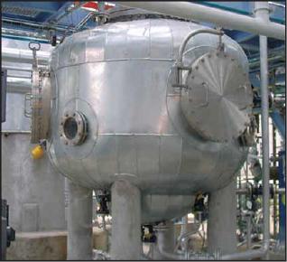
(Copyright Schulz+Partner GmbH, Teningen)
Advantages
- Reliable scale-up techniques.
- Can handle high flow rates.
- Ideal for processes with slow mass transfer.
- Intense mixing, resulting in small droplets for good mass transfer.
Disadvantages
- Large amounts of floor space required.
- Only systems with a few stages are economical.
- Large amounts of valuable material, such as the solvent, are tied up during the process.
- Poor solvent conservation.
Centrifugal
Centrifugal liquid-liquid extractors are quite versatile in their design and applications.
General Information
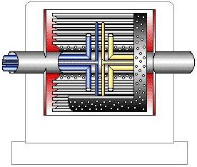
In centrifugal liquid-liquid extractors, the heavy and light streams flow counter currently. The heavy phase enters near the center of the extractor, and the light phase near the edges.
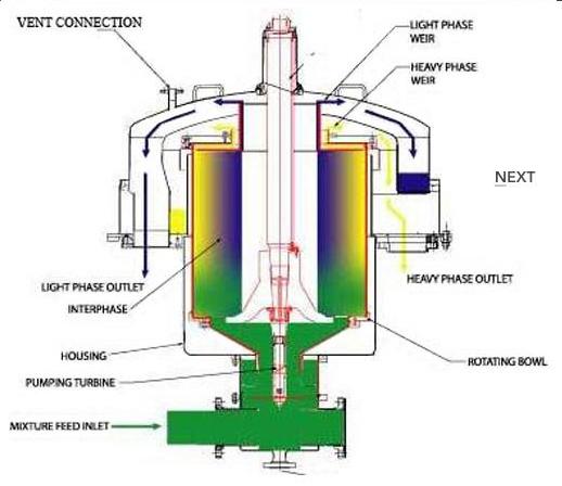
Centrifugal forces cause the heavy components to flow outward, resulting in contact, mass transfer, and separation. Droplet formation occurs in the body of the extractor through perforated concentric cylinders, enhancing the separation.
Tubes extending to the periphery serve as exit tubes for the heavy components, while the light components exit through inner tubes.
Equipment Design
There are two main centrifugal extractor designs. The first is a horizontal barrel compartment with two inlets and two outlets, as shown above in the animation. Droplets are formed as the liquids move through perforated concentric cylinders.
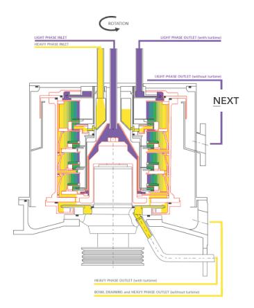
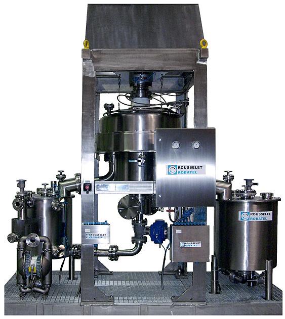
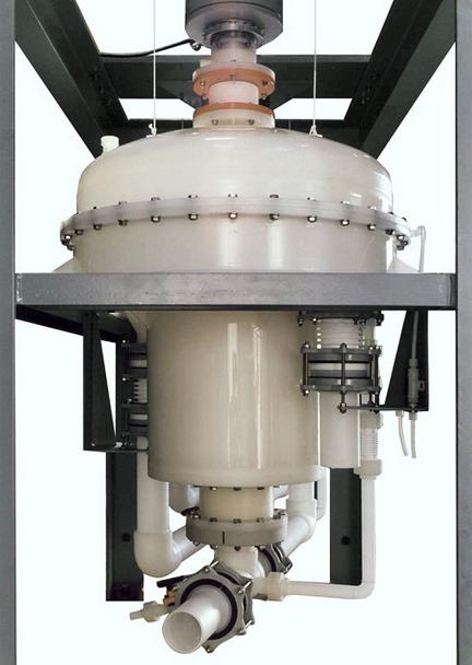
The second design is a vertical design that brings the two liquids into the middle of the extractor, with the heavy components forced to the periphery. Weirs inside the extractor ensure that the light phase exits separately from the heavy phase. On the left is an example of a process flow diagram of a liquid-liquid centrifugal separator. On the right is a cross-sectional diagram of an industrial scale multi-stage centrifugal extractor.
(Copyright ROBATEL, Inc., Pittsfield, MA)
Usage Examples
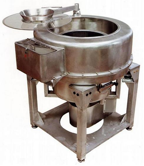
Due to the centrifugal extractor’s excellent ability to deal with liquids with small density differences, it has found much success and uses in the pharmaceutical, food processing, petroleum, chemical, and environmental industries.
The picture on the right is an example of a continuous centrifuge for de-watering food products. On the left is an example of an oil and water separator.
(Copyright ROBATEL, Inc., Pittsfield, MA)
Advantages
- Low residence time
- Can handle liquids with low-density differences
- Small space requirement
Disadvantages
- Expensive
- High speeds require maintenance on mechanical parts
- The low number of contact stages
Columns
Non-Agitated
Non-agitated column liquid-liquid extractors have no moving internal parts.
General Information
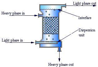
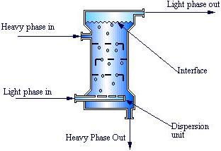
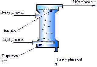
Non-agitated column liquid-liquid extractors are the simplest extractor columns, in that they contain no mechanical parts to induce mixing or droplet formation. Mass transfer is dictated by the column internals. The schematic shown on the left is of a sieve tray column, and that to the right is a spray column. The third most common design, a packed column liquid-liquid extractor, is shown above.
Equipment Design
Spray column liquid-liquid extractors are the simplest of the column designs. The dispersed phase is introduced via a nozzle either at the top or the bottom of the column, depending on whether the heavy phase or light phase is being dispersed. The continuous phase enters the opposite end of the column, resulting in mass transfer through the vertical counter-flow of the two phases. There is no dispersion-coalescence cycle inside the column, resulting in very low efficiency for spray columns. Spray columns work best for fluids containing large suspended solids.
Sieve tray liquid-liquid extractors are similar to the sieve tray columns described in the Distillation Columns section of this encyclopedia. The column is comprised of several perforated trays along with either downcomers or upcomers, depending on which phase, heavy or light, is chosen to be continuous. The original dispersion is performed by a nozzle, as in spray columns. Cross-flow contact occurs between each tray.
Sieve tray columns are stagewise contractors due to the coalescence of the dispersed phase between trays and its redistribution through the perforations in the tray. It is important that the internals be coated with the continuous phase to avoid efficiency dampening the coalescence of the dispersed phase. The droplets coalesce on the surface if the surface is coated by the dispersed phase, as shown on the left side of the picture below. This lowers the mass transfer for the column. Droplets will retain their form if the surface is coated with the continuous phase.
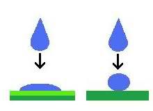
The animation below demonstrates a sieve tray liquid-liquid extractor. The lighter fluid, typically the solvent (red), enters from the bottom and flows up while the heavier fluid, the feed (blue), flows downward and extracts the desired product or waste.
Packed column liquid-liquid extractors are also similar to those seen in other separations sections of this encyclopedia. The packing, which assists in droplet formation, can either be structured in a mesh net or randomly placed in the column. Dispersion is accomplished with a nozzle at the top or bottom of the column, depending on whether the heavy or the light phase is being dispersed. As in sieve tray columns, the internals of the column need to be coated with the continuous phase.
Usage Examples
Non-agitated liquid-liquid extractors have found their niche in several different industries, including the petrochemical and water desalting and purification industries.
Advantages
- Spray columns are inexpensive.
- Sieve tray columns can handle a very sizeable throughput.
- Sieve tray columns have had good success with scale-up procedures.
- Packed columns are highly efficient when only a few stages are needed.
Disadvantages
- Spray columns are very inefficient.
- Sieve tray and packed columns can suffer from solids plugging.
- Packed columns have lower throughput due to the packing.
- Packed columns are hard to scale up accurately.
- The initial dispersion is a concern for packed columns, to avoid channeling.
Agitated
Many agitated column designs are used for liquid-liquid extraction. Only a few of the more popular designs will be explored in this section.
General Information
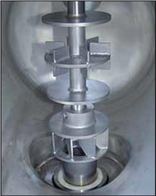
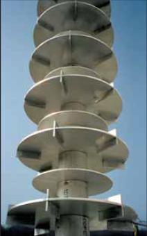
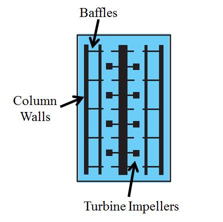
Agitated columns contain some type of mechanical device to agitate the liquids as they pass through the column. Rotating and reciprocating mechanisms are the most common methods for creating and maintaining dispersion throughout the column. The diagram below to the right shows the interior of an agitated column and the picture on the right is an agitator used in an extraction column.
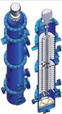
(Copyright Schulz+Partner GmbH, Teningen)
Equipment Design
Baffled mixing segments are common to all baffled column extractors. Turbine impellers rotate between a set of baffles, creating several mixing zones along the column length. The mixed liquids move to the outside sets of stator baffles, where they can separate out and move up or down to the next stage. The baffles help reduce axial mixing, creating several mixing zones to increase mass transfer. The Scheibel and the Oldshue-Rushton columns are common baffled designs.
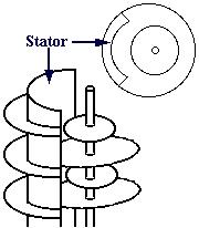
Rotating Disk Contactors (RDC) and Asymmetric Rotating Disk Contactors (ARDC) are other types of agitated column extractors. The ARDC seen in the animation is characterized by the off-center rotating shaft.
The heavy phase enters the top of the extractor and mixes with the light phase in the top mixing region, composed of a rotating disk. The two phases then enter the external settling stage, where they separate. The heavy phase then travels down to the next mixing region. This mixing-settling action continues down the length of the column. Individual mixing regions are separated by baffles, and the mixing and settling regions by a stator. A stator is a portion of a cylinder that separates the two regions while allowing transport between the two.
Reciprocating liquid-liquid extractors are also common agitated column extractors. Dispersion of the phases occurs through perforated plates that oscillate vertically inside the column. Occasional baffles along the column assist in reducing axial mixing and fluid movement.
Usage Examples
Agitated column liquid-liquid extractors are used to purify water by extracting out impurities such as acetic acid and acetone.
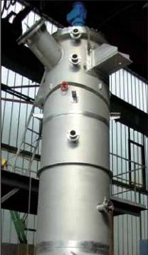
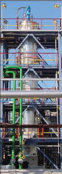
Agitated extractors are also used in biotechnical and environmental industries. The picture below shows an extractor in a plant. The column below has the ability to adjust the cross-sectional area and the agitator speed, which can optimize droplet size. This flexibility allows the column to maximize efficiency.
Advantages
- Mechanical parts result in good dispersion.
- Little axial mixing compared to non-agitated columns.
- Karr column extractors can handle higher throughputs than other agitated columns.
Disadvantages
- Repair of internal mechanical parts can cause process delays.
Pulsated
General Information
Pulsated column liquid-liquid extractors are unique in that they do not contain internal mixing elements. These extractors are often classified as agitated columns due to the need for an external energy source. The pulsating device uses the energy to send pulses into the fluids, enhancing mass transfer. The picture below shows a sieve tray pulsated column.
Equipment Design
The most common pulsated columns consist of a sieve tray or packed bed column design with a pulsating device. The diagram below shows a pulsated column that utilizes perforated plates. The pulsating device is on the outside of the column, which simplifies maintenance and repair.
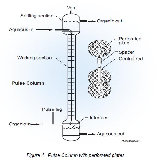
Liquid-Liquid Extraction Equipment)
Advantages
- Increases efficiency two-fold
- No internal mechanical parts make repairs easy
Disadvantages
- Packing in a packed column hinders the flow
- More expensive than non-agitated columns
Graesser
General Information/Equipment Design
Known as the raining bucket contactor, the Graesser extractor is considered an agitated column design. The buckets, attached to internal rotating disks, pick up a phase as the bucket breaks through the interface. As the disks rotate, they cause the phase to exit the bucket and disperse into the other phase. The mass transfer occurs as the droplets move through this other phase due to density differences.
The immiscible phases move from one portion to the next through the gap between the rotating disks and extractor shell, as depicted by the blue and yellow arrows. Slow rotating speeds and low flow rates increase mass transfer efficiency.
Advantages
- Inexpensive
- Simple design compared to other extractors
Disadvantages
- Inefficient at high flow rates
Acknowledgements
- Office of Scientific and Technical Information
- ROBATEL, Inc., Pittsfield, MA
- Schulz+Partner GmbH, Teningen
References
- Bailes, P.J., C. Hanson, and M.A. Hughes “Liquid-Liquid Extraction: The Process, the Equipment.” Chemical Engineering Magazine Separation Techniques 1: Liquid-Liquid Systems. 1980: 217- 231. Print.
- Bravo, Jose L., et al. Fluid Mixture Separations Technologies for Cost Reduction and Process Improvement. New Jersey: Noyes Publications 1986. Print.
- Cusack, Roger W., Pierre Fremeaux, and Don Glatz “A Fresh Look at Liquid-Liquid Extraction: Part One: Extraction Systems.” Chemical Engineering February 1991: 66-76. Print.
- Cusack, Roger W., Pierre Fremeaux, and Don Glatz “A Fresh Look at Liquid-Liquid Extraction: Part Two: Inside the Extractor.” Chemical Engineering March 1991: 132-138. Print.
- Cusack, Roger W., and Andrew Karr “A Fresh Look at Liquid-Liquid Extraction: Part Three: Extractor Design and Specification.” Chemical Engineering April 1991: 112-119. Print.
- Humphrey, Jimmy L., and George E. Keller II. Separation Process Technology. New York: McGraw-Hill 1997. Print.
- Perry, Robert H., and Don W. Green. Perry’s Chemical Engineers’ Handbook. 7th ed. New York: McGraw-Hill, 1997: pp. 15-22 – 15-47. Print.
- Reissinger, K. -H., and Jurgen Schroter “Selection Criteria for Liquid-Liquid Extractors.” Chemical Engineering Magazine Separation Techniques 1: Liquid-Liquid Systems. 1980: 247-256. Print.
Developers
- Michael Edison
- Steve Wesorick
- Matthew Robertson
- Joseph Palazzolo
- Keith Minbiole

