Mass flowmeters measure flow in one of two ways: inferentially or directly. Inferentially means density and flow rate are measured independently. Coriolis and thermal meters, shown below, are both direct mass flowmeters. The equipment sections below covers general information, equipment design, usage examples, and advantages/disadvantages.
Coriolis
In Coriolis meters liquid travels through a vibrating U-shaped or straight tube.
(Copyright Emerson Process Management, Chanhassen, MN)
General Information
Coriolis mass flowmeters are true mass meters in that they directly measure mass flowrates, as opposed to volumetric flowrates. These flowmeters operate based on the Coriolis principle. The Coriolis principle is the idea that something moving linearly in a rotating frame experiences acceleration.
Imagine a ball traveling horizontally through a pipe, as shown on the left. Now suppose the pipe rotates around a horizontal axis, as on the right. The pipe would inflict a force on the ball, which the ball would counter. These conflicting forces govern the operation of Coriolis mass flowmeters.
Equipment Design
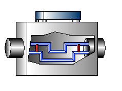
Coriolis meters typically consist of a U-shaped flow tube outfitted with a magnetic driver and two electromagnetic sensors. The driver, located at the bend of the tube, causes the tube to vibrate slightly up and down, much like a tuning fork.
As fluid flows into the U-tube meter, it’s forced to take on the tube’s vertical movement. As the tube swings upward, the entering fluid resists the upward motion by pushing down on the tube. When this fluid exits the tube, it resists having its vertical motion decreased by pushing up on the tube. This causes the tube to twist. Fluid entering the tube during its downward swing causes it to twist in the opposite direction.
The twisting tube serves as a rotating frame. Electromagnetic sensors, located at the sides of the tube, are stationary reference points from which the tube velocity is measured. The tube velocity, due to Coriolis acceleration, is an indicator of the linear velocity of the fluid. Thus the amount of twist is directly proportional to the mass flow rate of the fluid in the tube.
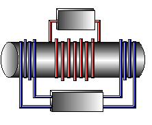
Straight-tube Coriolis meters are becoming more popular because they are easier to clean than U-tube meters and are installed in-line with piping. They operate in much the same way as U-tube Coriolis meters. The magnetic driver forces the tube to oscillate, and fluid flowing through the tube pushes opposite the tube’s motion, causing it to distort.
Usage Examples
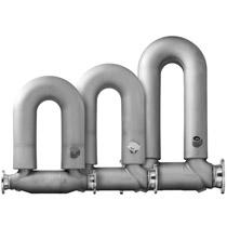
Coriolis meters are the most versatile flow devices on the market today. U-tube Coriolis meters are used to meter polymer solutions, dyes and paints, chemicals and petrochemicals, and pharmaceuticals. The U-tube Coriolis meter shown on the left ensures an accurate reaction in a chemical process. Those on the right are used in refinery applications to measure mass and volume flow, liquid density, and temperature of natural gas liquids.
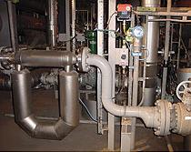
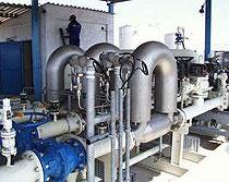
(Copyright Emerson Process Management, Chanhassen, MN)
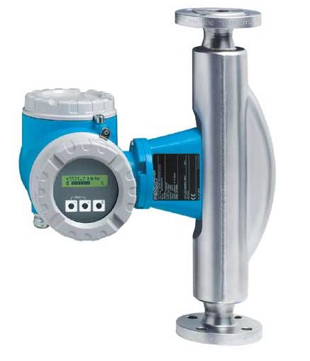
Straight-tube Coriolis meters are often used to meter a variety of food products, such as sugar solutions, milk, and chocolate. They are also used in the chemical and petrochemical, pharmaceutical, and pulp and paper industries. The straight-tube meter pictured on the left is used to measure carbon dioxide for a beverage industry and the meter pictured on the right is used to measure precise amounts of salad dressing.
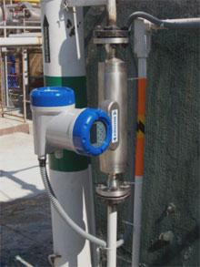
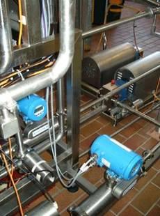
(Copyright Krohne, Inc., Peabody, MA)
Coriolis meters are often used in applications where a high degree of accurate control is required and mass flowrate is more important than volumetric flowrate. Examples include reactor charging, batch operations, and blending.
Advantages
- Devices can accommodate liquid and liquid/solid flow.
- Can be constructed from a variety of materials.
- Measures independently of flow conditions (temperature, pressure, density, viscosity, flow profile, flow regime ).
- Straight-tube: minimal flow obstruction and pressure drop.
- Do not require long runs of straight pipe.
- Accurate within 0.05 %.
- Can be used in pipes up to 12 inches in diameter.
Disadvantages
- Extreme temperatures may affect oscillating capabilities of the tube.
- Cannot handle high solids content.
- U-tube: subject to clogging and disrupts the flow.
- U-tube devices have relatively high-pressure drops.
- More expensive than most flowmeters.
- Can’t handle entrained gases.
- Sensitive to system vibration.
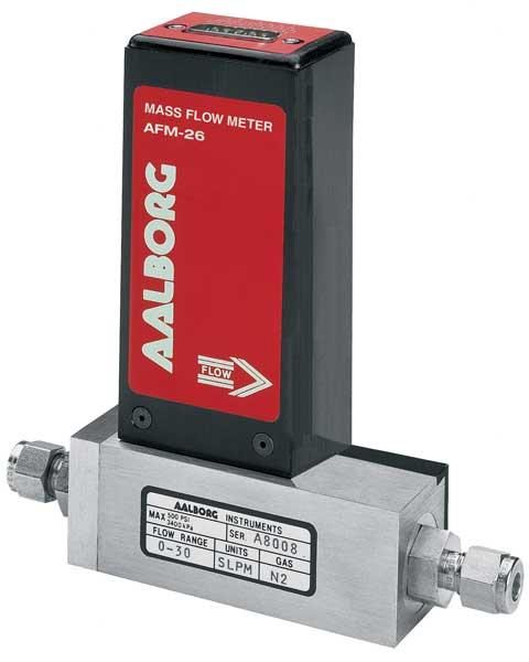
Thermal
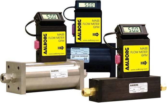
Thermal mass flowmeters use heat transfer to measure flow rate.
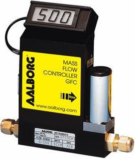
(Copyright Aalborg Instruments & Controls, Inc., Orangeburg, NY)
General Information
The operation of thermal mass flowmeters is based on the tendency of molecules to absorb heat.
As gas molecules flow through the meter, heat is transferred from the meter to the gas. The more gas flows by, the more heat is lost by the meter.
(Copyright Aalborg Instruments & Controls, Inc., Orangeburg, NY)
Equipment Design
The most common type of thermal mass flowmeter is the heated tube. A portion of gas flow is diverted through a sensing tube such as the one in the picture. The tube has two sensors that conduct heat to the gas via a wire coiled around the tube, as shown in the schematic. When flow occurs, gas molecules carry heat from the upstream coil to the downstream coil. Thus, less heat is transferred from the second coil than from the first one, and a temperature gradient is generated.
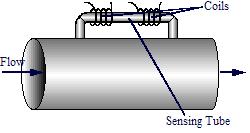
The difference in temperature between the sensors is directly proportional to the mass flow rate of the gas. The corresponding change in resistance of the coils is used to determine and display the mass flow rate.
Hot-wire and hot-film anemometers operate similarly to the heated tube except that they use a platinum wire or film directly exposed to the gas flow instead of coils.
Immersion probe meters, also known as insertion probe meters, consist of two sensors immersed in the fluid flow. One sensor measures the ambient temperature of the gas, and the other sensor is maintained at a constant temperature of 75 – 100°F above the gas temperature.
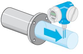
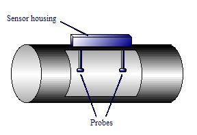
Immersion Probe Meter
As the gas flows past the heated sensor, heat is transferred from the sensor to the gas. The amount of heat transferred from the sensor is proportional to the mass flow rate. The amount of current required to keep the sensor at its designated temperature is used to determine the flow rate.
Usage Examples
Thermal mass flowmeters are used only in gas applications. They are most often used in boiler control, pneumatics, and compressed air accounting, but they also have applications in the pharmaceutical, food, and beverage industries. The thermal flow meters below are used to meter the flow of nitrogen gas and are available with Nitrogen flow rates from 10 mL/min to 1000 L/min.
Advantages
- Unaffected by temperature, pressure, density, or viscosity within regular operating limitations
- Can be calibrated to measure a variety of gases over a wide range of flowrates
- Easy to install and maintain, no moving parts
- Excellent low-flow sensitivity
- Do not restrict flow in any way
Disadvantages
- Extremely sensitive to solid particles, the gas must be very clean
- Point measurements only so provide no information on the flow profile
- Special, much more expensive, designs required for liquid flow
Acknowledgements
- Aalborg Instruments & Controls, Inc. , Orangeburg, NY
- Emerson Process Management , Chanhassen, MN
- Endress + Hauser Inc., Greenwood, IN
- Krohne, Inc. , Peabody, MA
References
- Digiacomo, Ronald W., “Measuring Flow.” Chemical Engineering, 7(2011): 30 – 34.
- Omega Complete Flow and Level Measurement Handbook and Encyclopedia, Vol. 29. USA: Omega Engineering Inc., 1995: D-3 – D-6, Z-14 – Z-15. Print.
- McCabe, Warren L., Smith, Julian C., and Peter Harriot. Unit Operations of Chemical Engineering. New York: McGraw-Hill, 1993: 228 – 229. Print.
- Miller, Richard W. Flow Measurement Engineering Handbook. 3rd ed. New York: McGraw-Hill, 1996: 6.32, 6.34 – 6.38. Print.
- Perry, Robert H., and Don W. Green. Perry’s Chemical Engineers’ Handbook. 7th ed. New York: McGraw-Hill, 1997: 8-49, 10-10, 10-19. Print.
Developers
- Erica Mauter
- Joseph Palazzolo
- Matthew Robertson
- Kelsey Kaplan
- Andrea Roberts
- Fritz Hyde