Level measurement devices can detect, indicate, and/or help control liquid or solid levels. Level measurement devices can be separated into two categories: direct or mechanical measurement and electronic measurement. The device used for a process is based on the material used as well as its corrosivity and toxicity.
Level measurement devices can be used for continuous monitoring of fluid level, or for point-level monitoring. In point-level monitoring they are used to determine if the fluid level has exceeded a high point, which could cause a spill, or gone below a low point, which could mean the system is close to running on empty.
Direct Measurement
Floats
Floats can be used to indicate or control the level of a liquid.

General Information
A float resting on a liquid surface will rise and fall with changes in liquid level.
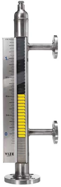
In some level indicator designs, the float is magnetic and changes in position are indicated on an external indicator, such as on the magnetic float level indicator shown here.
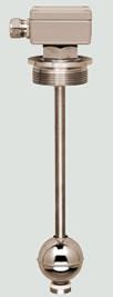
Floats can also be connected to a pivoted arm or pipe, as shown below. Generally, a level switch or controller is added to control liquid level. Just as in an indicator, changes in liquid level move the float. When the float reaches a predetermined level, a switch either stops or starts liquid flow.
Equipment Design
A magnetic float level indicator, shown in this schematic, consists of a float chamber, a float, and an external indicator tube.
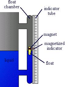
A float chamber is a column of pipe with connections to match the piece of equipment for which liquid level is to be measured.
The float moves up and down inside the chamber as the liquid level changes. Float type and material are determined by the properties of the liquid being measured.
The float contains a magnet. The transparent external indicator tube contains a magnetized indicator which is coupled with the magnet inside the float. The indicator moves up and down the indicator tube as the float moves up and down with liquid level changes.
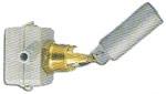
Float-type level indicators such as the one pictured above can be designed to control liquid level by adding a level switch to the float indicator. Two main types of level switches are used: magnetic and mercury .
Usage Examples
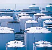
Float level indicators and switches may be applied to level measurement and control of a wide variety of liquids, such as petroleum products, water, wastewater, acids, caustics, or fuels.
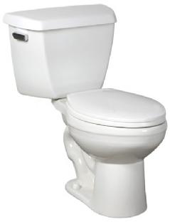
An everyday use of float level indicators and switches is the float in a toilet, such as the one pictured below.
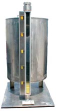
They are also commonly used to indicate and control liquid level in tanks or drums. Pictured below is a magnetic gauge attached to a process vessel.
Advantages
- Indicators easy to read from a distance.
- Customizable for different applications.
- Low cost.
- Easy to install.
- Simple to operate.
Disadvantages
- Prone to corrosion if liquids and materials are not compatible.
- Does not work properly if placed in a slurry or liquid solution with surface particles.
- Steam can affect measurement
- Buildup of material on the float causes changes in weight displacement.
- Can only be used with non-freezing fluids.
Rotary
General Information/Equipment Design
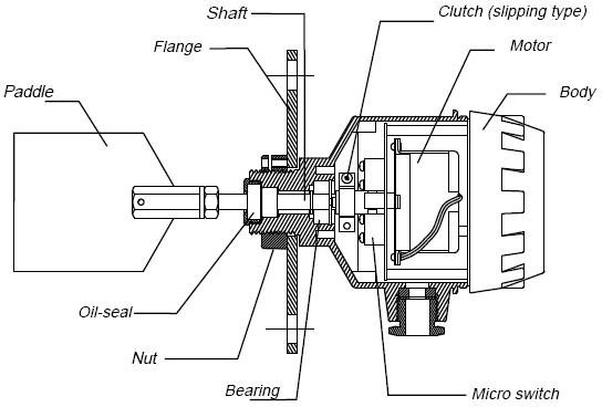
Rotary level indicators indicate and control level with a rotating paddle. Pictured below are a variety of rotary level indicators.
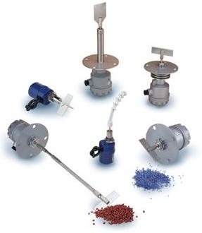
They are comprised of a head in which a geared motor is mounted. A paddle attached to the motor rotates slowly at 1 rpm. When material impedes rotation of the paddle, the motor shuts off and either an alarm sounds, indicating flow has reached a certain level, or a switch shuts off flow. When the material level drops, the paddle rotates again.
Usage Examples
Rotary level indicators can be used with powders, plastics, granular products, grains, cement, sand, fillers, pigments, wood dust, and particulate materials. They are used to control the level of these materials in silos, tanks, hoppers, or bins. They can be mounted above the material or on the side to provide high or low level control. Pictured here is a rotary level monitor used in bulk solids storage vessels.
These indicators must be periodically checked to make sure that dust does not collect between the seals and bearings, stopping the motor, even in the absence of material.
Vibrating
General Information/Equipment Design
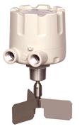
Vibrating level indicators are used for both level indication and control. In this type of level indicator, a tuning fork-like rod vibrates.
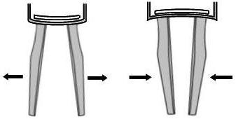
When material comes into contact with the rod, the vibrations are damped. The ceasing of vibrations indicates that material has reached the level of the indicator. Generally, this operates an alarm or switch that stops material flow. When the rod is free of material, it will vibrate again.
(Pictures copyright Emerson Process Management, St. Louis, MO)
Usage Examples
Vibrating level indicators are most often used for measuring powder or granular solids. They can be used to indicate and control level in hoppers, bins, or silos, such as the ones pictured here. Generally, they are used for high-level measurement.
Vibrating level indicators should not be used on material that will pack between the two prongs of the fork-like rod. If this occurs, vibration will cease whether or not material is surrounding it.
Advantages
- Can be used in slurries and particle laden solutions.
- Corrosion resistant.
- Able to be installed in any direction.
Disadvantages
- Requires constant supply of power.
Dipsticks
General Information/Equipment Design
Dipsticks are widely used for quick and easy level measurement for liquids in hard to reach places. The design is simple. They consist of a metal strip connected to a handle. The handles are usually plastic or metal. The metal strip has markings on it to indicate liquid level.
The dipstick is inserted into the container in which the level is to be measured. Then after a couple minutes, or enough time to allow the liquid to settle, the dipstick is removed and the level can be read off the markings on the metal strip . If they are used properly, they can give very accurate readings.
Usage Examples
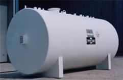
The most common and well-known application of dipsticks is the measurement of oil levels in cars. Dipsticks are also used to measure levels in tanks, such as the one pictured here.
Advantages
- No moving parts to clog or wear.
- No electronics to fail.
Disadvantages
- Must be used properly to give accurate reading.
- Each measurement requires person to perform time-consuming operation.
Electronic Measurement
Ultrasonic
Ultrasonic level measurement utilizes the propagation time of sound waves.
(Pictures copyright Emerson Process Management, St. Louis, MO)
General Information
Ultrasonic level measurement units consist of a piezoelectric crystal stored inside a transducer and used to convert an electrical signal into sound energy. The sound energy is released toward the material, in this case a fluid, and is reflected back to the transducer which now acts as a receiver and converts the sonic energy back into an electrical signal. Finally, an electronic signal processor analyzes the returning signal and calculates the distance between the transducer and the material.
Equipment Design
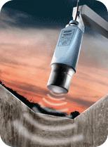
The ultrasonic transmitter can be mounted above the liquid or solid, as shown here. A sound wave is transmitted from the ultrasonic unit and echoes off the surface. The propagation time is proportional to the distance between the surface and the unit.
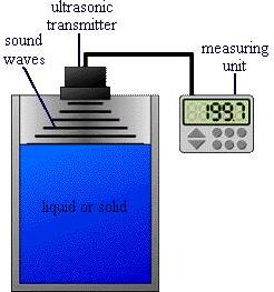
Above-level units must be placed at a minimum distance above the surface to work properly. Hence, maximum surface level must be taken into account when placing the unit. In addition, the propagation time will vary with the air temperature above the surface. Most units are equipped with a temperature sensor (not shown here) to monitor temperature.
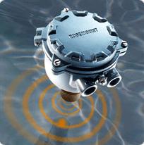
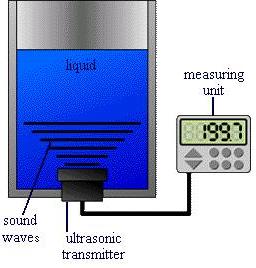
Ultrasonic level indicators can also operate below the liquid level. In this arrangement, sound waves are sent up through the liquid and reflected back from the surface. As in the other arrangement, the propagation time of the sound waves is proportional to the distance travelled.
This arrangement, shown below, is only used for liquid level measurement. It is advantageous when foam or particles on the liquid surface might affect reflection of the sound waves. In addition, air temperature will not affect the propagation of sound waves. Hence, temperature monitoring and control are not as critical.
Usage Examples
The ultrasonic unit is normally placed above the material if sound wave propagation through the material will be difficult. This is the case for monitoring solids, such as powders or granules in silos, hoppers, bins, or even open piles. Some common placements of ultrasonic devices are shown below for, from left to right, tanks, open channels, and open air.
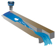
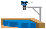
(Pictures copyright Emerson Process Management, St. Louis, MO)
Placement above the fluid is also used if it is undesirable for the unit to come in contact with the liquid, such as when monitoring sewage levels.
Arrangements in which the unit is placed at the bottom of a tank or vessel are only useful for measuring liquid level.
Ultrasonic level measurement is commonly used in effluent, surge, and slurry tanks to monitor volume. Ultrasonic units are also used in process tanks where they act as an alarm signaling low and high levels.
Advantages
- Provide an almost continuous reading.
- Under most conditions, the unit is out of contact with the material, avoiding contamination and corrosion.
- Can be used to measure the level of the interface between two liquids or a liquid and a settled solid.
- Easy to set up.
- Self cleaning.
- No moving parts.
- Low maintenance cost.
- Unaffected by different dielectric or vessel shape.
- Some are encased with durable thermoplastic and fluoropolymers which allows them to be used with aggressive chemicals.
Disadvantages
- Relatively expensive, so its use is limited to special applications.
- Dense vapor, dust, and foam can affect the most advanced devices.
- Temperature must not exceed 150°C (300°F).
- Pressure must not exceed 8 bar (116 psi).
Capacitance
Capacitance level measurement measures changes in capacitance to indicate levels of liquids or granular solids.
General Information
A capacitor is composed of two adjacent metal plates insulated from each other by a dielectric . The capacitance depends on the area of the plates and the distance between them.
In level measurement, a capacitor is formed when a metal rod, or electrode, is inserted in a metal tank and insulated from the tank walls by a dieletric. Presence of a liquid or granular solid alters the capacitance between the electrode and the walls. Changes in capacitance indicate liquid or solid level.
Equipment Design
The electrodes and insulators, or dielectrics, used are tailored to the liquid or solid being monitored. Shown here is a schematic of a basic capacitance level indicator setup, including a cutaway schematic of a capacitor.
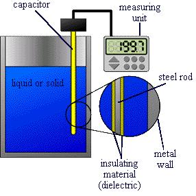
Electrodes are generally steel rods or flexible cables . For insulating liquids or solids, the electrode is usually a bare rod or cable and the dielectric is the liquid or solid being measured.
For aqueous solutions in which the solution is not insulating, the rod or cable is covered with an insulating material , which becomes the dielectric.
Electrodes are mounted vertically and are long enough to cover the length over which level indication is required.
Usage Examples
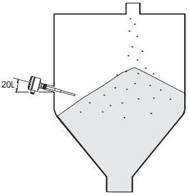
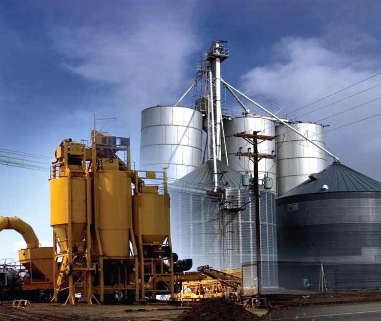
Capacitance level indicators are commonly used to measure granular solid levels. For example, they might be used to indicate powder or grain levels in hoppers or silos, such as the ones pictured here.
Another common application is measuring liquid level in a tank, tower, or reservoir. In such vessels the indicator may also be used to control the liquid level by controlling the pump that feeds the liquid into the vessel.
Advantages
- No moving parts.
- Compatible with vast range of liquids, powders, and granular solids.
- Compatible with vast range of vessel shapes.
- Relatively low cost compared to other electronic measurement methods.
Disadvantages
- Rely on uniform contact being maintained between liquids or solids and electrode.
- Must be careful to select correct electrode for application.
Optical
General Information/Equipment Design
An optical level indicator uses reflection of light to sense level. It consists of both a light source and a sensor/receiver. Light (red) is reflected back to the sensor by the conical tip of a quartz light conductor or prism. When material is present, such as when the material level rises, light is refracted into the material. The sensor senses the change in the refraction of light waves and sends a signal to shut off material flow.
Usage Examples
An optical level indicator, shown here, is used mainly for liquid level indication and control. Viscous liquids or liquids that may crystallize are generally not monitored using optical level indicators.
Powdered or granular solids are not measured using this type of indicator because dust could collect on the indicator.
Advantages
- Only glass window is within tank, nothing else contacts liquid or protrudes into tank.
- Relatively low cost.
- Small sized device.
Disadvantages
- May not work well with opaque and highly reflective materials.
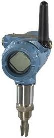
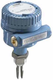
Radio Frequency
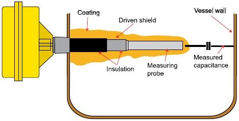
General Information/Equipment Design
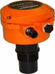
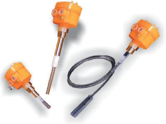
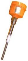
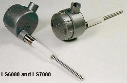
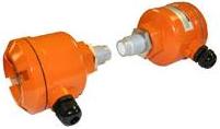
In radio frequency level indicators, such as the ones shown here, a radio frequency is applied to a probe. When liquid or solid is brought close to the probe, the resonant frequency is altered. The change in frequency indicates level.
Below is a diagram of a radio frequency level measurement device inside a vessel. There is a radio frequency signal between the stainless steel probe and the vessel wall. If there is just air between them, then the probe has a dielectric value of 1.0, and the capacitance around the probe is measured with electric circuitry. When material deplaces the air, the dielectric value increases, and an alarm can be triggered to sound.
Usage Examples
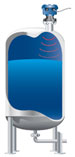
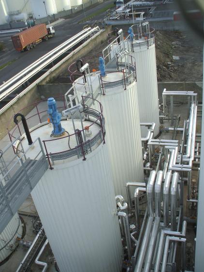
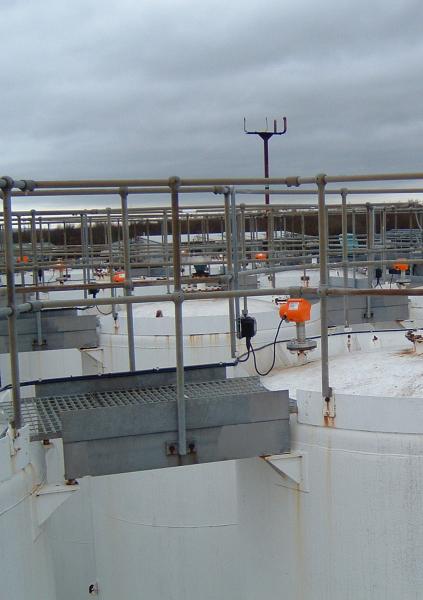
Radio frequency level indicators can be used to indicate level in bins, silos, tanks, hoppers, and other vessels. They can measure level of powder or granular solids as well as liquid level. Pictured below are radio frequency indicators placed above tanks to measure the liquid or solids insides, such as plastics, grains, powders, flakes or oils.
(Pictures copyright Hycontrol Ltd, Worcestershire, UK)
Microwave
General Information
There are normally two parts to a microwave level switch; a transmitter and a receiver, which are placed on opposite walls of the tank. The transmitter emits bursts of microwaves at a frequency of 200 s -1 . The receiver picks up the energy, unless the path is blocked by a sufficiently reflective or absorbent material. The sensitivity of the receiver can be adjusted depending on the material in the tank.
Usage Examples
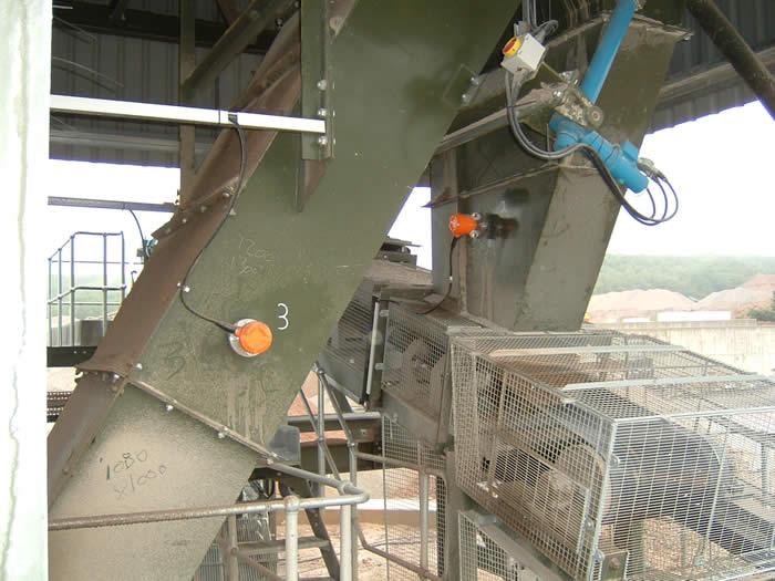
Microwave level switches can be used for a variety of materials including, granules, flakes, stones, cement, liquids, and pastes. Below are microwave detectors on a chute, and are used to detect blockage. If everything is moving as it’s supposed to, the detectors will not pick up on the moving material, but if something is blocking the chute and material builds up, then the microwave switch detect the change and sounds an alarm.
Acknowledgements
- American Standard Brands, Piscataway, NJ
- Babbitt International, Inc., Houston, TX
- Emerson Process Management, St. Louis, MO
- Gems Sensors Inc., Plainville, CT
- Granzow Inc., Charlotte, NC
- Hycontrol Ltd, Worcestershire, UK
- Monitor Technologies LLC, Elburn, IL
- Process Level Technology Ltd., League City, TX
- Service Welding & Machine Company, Inc., Louisville, KY
- Vize, LLC, Houston, TX
References
- Cartier, Marc. “A Look at Liquid Level.” Chemical Engineering . 5 (2002): 93-95. Print.
- Fowles, Graham. Flow, Level, and Pressure Measurement in the Water Industry. Oxford: Butterworth Heineman, 1993. 191-219. Print.
- Lazenby, Brian. “Level Monitoring and Control.” Chemical Engineering 14 Jan. 1980: 88-96. Print.
- LePree, J. (2018, April). Level Measurement: One Size Does Not Fit All. Chemical Engineering Essentials for the CPI Professional, 20-24. Print.
- Perry, Robert H. and Don W. Green. Perry’s Chemical Engineers’ Handbook . 7th ed. New York: McGraw-Hill, Inc., 1997: 8-49. Print.
- Schmidt, Karlheinz. “Level measurement Technologies For the CPI” Chemical Engineering July 2008: 34-37.
Developers
- Melissa Schlosser
- Steve Wesorick
- Kelsey Kaplan
- Abigail Nalbandian
- Henry Chen
- Austin Potter