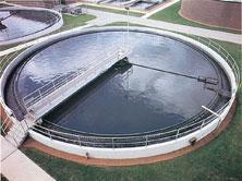
Thickeners and clarifiers are both used to separate liquids and solids by settling. Thickeners are used to concentrate solids, while clarifiers are used to purify liquids. Clarifiers can be circular clarifiers, pictured on the left, or parallel plate clarifiers, pictured on the right.
(Copyright Water Technologies Business Unit of Siemens Industry, Inc., Warrendale, PA)
(Copyright Monroe Environmental Corporation, Monroe, MI)
Circular Clarifiers
General Information
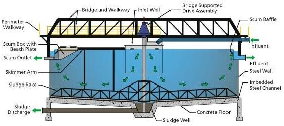
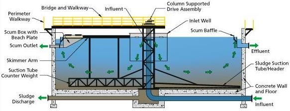
Thickeners and clarifiers use slowly rotating rake arms to separate solid particulate. A liquid feed with suspended solids is fed into a tank with a diameter of 5 to 500 feet. As the particles settle, angled rake arms move the concentrated slurry toward the center of the tank, where it is removed. Clear liquid overflows the top of the tank and is collected in a trough.
(Copyright Monroe Environmental Corporation, Monroe, MI)
Equipment Design
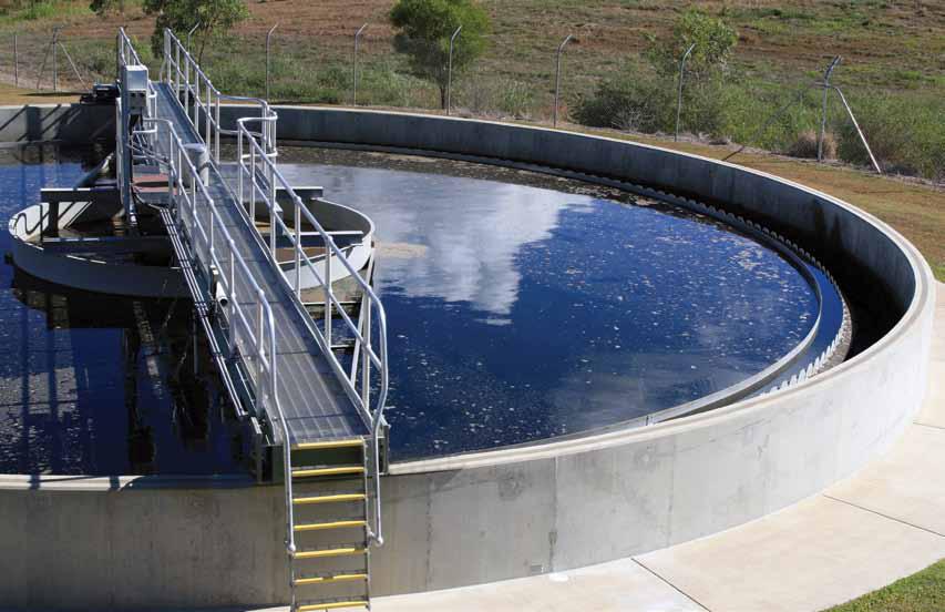
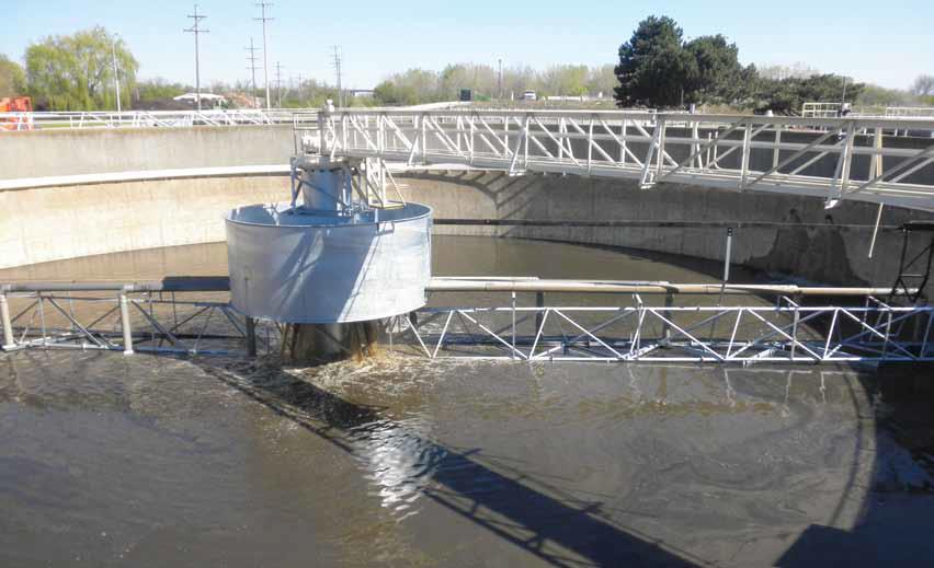
There are three main types of thickeners/clarifiers: bridge support, column support, and traction. In a bridge support thickener, such as the one shown below, the rakes and drive mechanism are suspended from a bridge that spans the diameter of the tank. They are usually only economical for diameters of fewer than 100 feet.
(Copyright Monroe Environmental Corporation, Monroe, MI)
The bridge-supported clarifier pictured above is used for primary wastewater treatment. After large objects and grit have been screened out of the water, raw wastewater is fed into the primary clarifier. In this stage, floating material and material that easily settles out will be removed, resulting in a homogeneous effluent that can be further treated biologically in the secondary clarifier, and a sludge discharge that can be treated or processed.
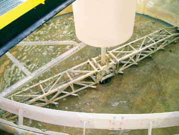
In column support thickeners, such as the one shown below, the drive and raking mechanisms are attached to a central column. The feed usually enters through an overhead pipe supported by an access bridge that leads to the center column.
(Copyright Monroe Environmental Corporation, Monroe, MI)
The column-supported clarifier pictured above is used for secondary wastewater treatment. In this stage, bacteria consume up to 90% of the organic matter in the wastewater. After the minimum removal standards for biochemical oxygen demand (BOD), total suspended solids (TSS), and pH are met, the effluent can be discharged to the environment or treated further.
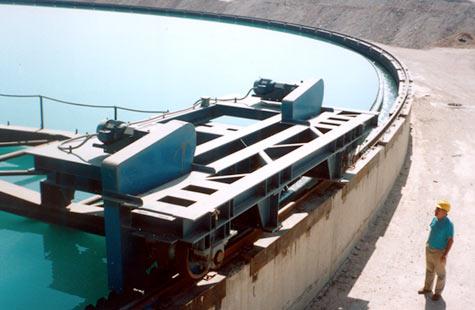
Traction units also have a center column, but the drive power is supplied by a trolley that rides along a track at the tank wall. Unlike center drives, traction drive units are able to efficiently provide a very high amount of torque for high-demand applications.
(Copyright FLSmidth, Denmark)
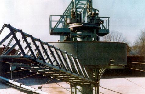
In the thickener shown below, cables control the height of the rake arms. When heavy sludge builds up at the bottom, the rakes are raised slightly. Once the blockage has been dispersed, the rake arms are lowered back to normal position. Adjustable rake arms increase operating efficiency by reducing maintenance downtime.
(Copyright Monroe Environmental Corporation, Monroe, MI)
(Copyright FLSmidth, Denmark)
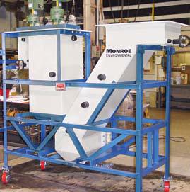
A thickener/clarifier drive unit supplies the torque to rotate the rake arms through the thick sludge. The drive is usually made of cast iron because of its durability.
Usage Examples
Thickeners and clarifiers are often used in water and wastewater treatment plants to remove solids, chemicals, microbes, and other impurities.
(Copyright Monroe Environmental Corporation, Monroe, MI)
Thickeners and clarifiers are also used in the paper industry, the uranium industry, and in alumina, coal, copper, and iron ore production.
Advantages
- Effective solid-liquid separation.
- Can be used for a variety of liquid-solid separations.
Disadvantages
- Inefficient for small-scale operation.
- Large initial investment.
- Requires a large installation area.
Parallel Plate Clarifiers
General Information
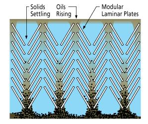
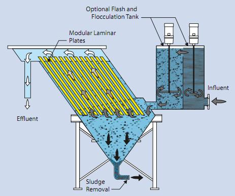
Parallel plate clarifiers are designed to create laminar flow, allowing gravity to separate heavier elements from the rest of the fluid, as shown below.
(Copyright Monroe Environmental Corporation, Monroe, MI)
Equipment Design
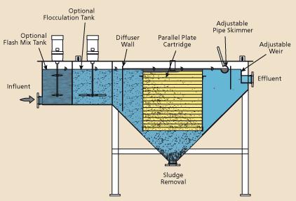
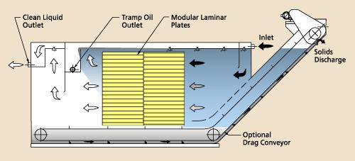
Parallel plate clarifiers can be structured horizontally or vertically. Horizontal parallel plate clarifiers can have a cone bottom configuration which is recommended to remove solids that cannot be transported with a conveyor. They also can be configured similar to a settling tank, with a drag conveyor that continuously removes settled solids. Diagrams of both configurations are shown below.
(Copyright Monroe Environmental Corporation, Monroe, MI)
(Copyright Monroe Environmental Corporation, Monroe, MI)
In horizontal clarifiers, raw material enters at one end of the tank and goes into a flocculation tank where the fluid is mixed and suspended particles are brought together to create larger and heavier particles that are easier to separate out. In the settling zone, fluid flows through plates that are typically spaced 1 to 4 inches apart. The effluent passes through weirs into collection troughs. Sludge that is settled out is removed through piping by means of pumps or hydraulic head pressure, or with the use of mechanical drag conveyors. The configuration used depends on the application.
Vertical parallel plate clarifiers operate using the same laminar flow principle, but the liquid flows vertically. The influent flows to the lower area of the laminar plate sections. Waste fluid flows up the plates under laminar conditions, and then particulates settle onto the plates and slide down to the removal area. The weirs at the top of the plate section maintain a balanced flow through the plates. Effluent flows out the top of the clarifier.
(Copyright Monroe Environmental Corporation, Monroe, MI)
Usage Examples
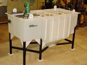
Parallel plate clarifiers are often used to separate solids and low-density liquids, such as oils. They can be suitable for many applications, including chemical processing, coolant systems, food processing, oil refinery, paper making, and industrial waste management. The horizontal clarifier pictured below operates at 40 GPM and is used to treat plating wastewater.
(Copyright Monroe Environmental Corporation, Monroe, MI)
Advantages
- Low space requirement.
- No moving parts in the settling area.
- No filter media is required.
Disadvantages
- Cannot be used for operations larger than 2000 GPM.
Acknowledgments
- FLSmidth, Denmark
- Monroe Environmental Corporation, Monroe, MI
- Water Technologies Business Unit of Siemens Industry, Inc., Warrendale, PA
References
- Geankoplis, Christie J. Transport Processes and Unit Operations. 3rd ed. Englewood Cliffs: Prentice Hall PTR, 1993: 825-829. Print.
- McCabe, Warren L., Julian C. Smith, and Peter Harriott. Unit Operations of Chemical Engineering. 5th ed. New York: McGraw-Hill, 1993. Print.
- McKetta, John J. “Solid Liquid Separation.” Encyclopedia of Chemical Processing and Design. 1995. Print.
- Perry, Robert H. and Don W. Green, Perry’s Chemical Engineers’ Handbook. 7th ed. New York: McGraw-Hill, 1997: 18-61 – 18-73. Print.
- Purchas, Derek B. and Wakeman, Richard J. Solid/Liquid Separation Scale Up. 2nd ed. London: Uplands Press LTD., Filtration Specialists LTD., 1986. Print.
- Schweitzer, Philip A. Handbook of Separation Techniques for Chemical Engineers 2nd ed. New York: McGraw-Hill, 1988: 4-128 – 4-141. Print.
- United States. Environmental Protection Agency. Office of Water. Primer for Municipal Wastewater Treatment Systems. Environmental Protection Agency, Sept. 2004. Web. 6 Aug. 2011.
- Walas, Stanley M. Chemical Process Equipment. Boston: Butterworth-Heinenmann, 1990. Print.
Developers
- Michael Fein
- Kelsey Kaplan