There are many types of instruments used to measure absolute or gauge pressure. Pressure measurement devices can be separated into two categories: mechanical and electronic.
Mechanical
Manometer
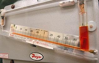
The height of the liquid in a manometer is directly proportional to the hydrostatic pressure . The picture below shows an inclined manometer.

General Information
The three major types of manometers are: differential, sealed-end, and open-end.
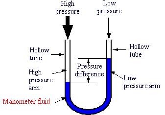
Differential manometer
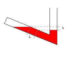
A differential manometer is different than a sealed-end or an open-end manometer in that the two ends are exposed to different points along the flow path.
The difference in fluid heights yields the pressure difference between the two points. The small difference in liquid heights is more easily measured along the angled line (“L”) than along the vertical stem (“h”).
Sealed-end Manometer
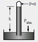
In sealed-end manometers the open end is open to the fluid of interest, while the closed end encloses a vacuum.
For example, in a barometer, atmospheric pressure, P atm , pushes some of the mercury from the reservoir into and up the glass tube. The height of the liquid column, h, then represents the atmospheric pressure.
In 2007 the European Union banned the use of mercury in barometers due to the high toxicity of mercury. They were followed in 2011 by the United States.
Open-end Manometer
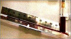
In open-end manometers one arm is exposed to the fluid being monitored, and the other arm is open to the atmosphere. The picture below shows an open-end manometer from a unit operations laboratory. It is actually over six feet tall, so only some parts are shown here.
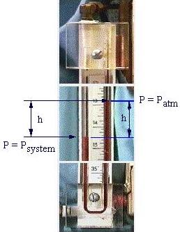
In this example, the system pressure is greater than atmospheric pressure. The gas in the left arm then pushes some of the liquid in the manometer into the other arm. The resulting height difference h represents the pressure difference between the system and the atmosphere.
Equipment Design
When the ends of the manometer tube are exposed to different pressures, the high pressure pushes down on the fluid and the level drops, forcing the fluid level to rise in the low pressure arm. The pressure difference can be determined from the difference in height. Click on the picture below for a hotspot on manometer fluid
Usage Examples
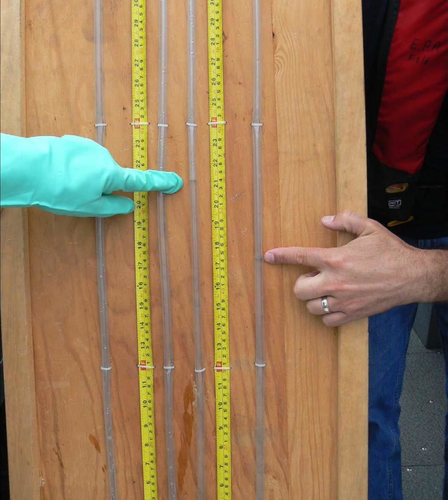
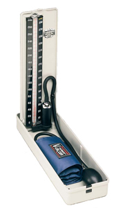
On the left the hydrostatic head or static head of a water manometer is used to measure the pressure between the surface water and groundwater. Manometers are also useful in the medical field. For example, the sphygmomanometer to the right is used to measure blood pressure.
Advantages
- Easy to read, height difference is proportional to pressure
- No moving parts
Disadvantages
- Cannot measure high pressures with great accuracy
- Small pressure range
- Contain fluids which can be dangerous when exposed to high temperatures, limiting manometers to low temperature systems
Pitot Tube
Besides measuring pressure, pitot tubes also measure velocity and are sometimes called velocity gauges or anemometers.

General Information
Placement of holes on the pitot tube greatly affects the type of pressure to be measured. For example, the schematic drawing below shows the pitot tube measuring both static and total pressure.
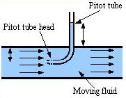
Equipment Design
A pitot tube can be placed along the streamline parallel to the moving fluid. At the head of the pitot tube is a tiny opening to allow minimum flow of the moving fluid. The fluid travels up the pressure indicating device, i.e. manometer. The manometer height then reflects the pressure in the moving fluid.
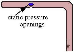
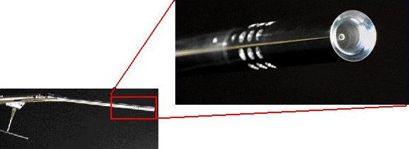
Other variations of the pitot tube, such as the one below, have holes on the sides instead of one in front to measure static pressure. The fluid outside of the tube forces the fluid within the tube up to the indicating device where the pressure can be read.
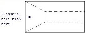
Below on the left are examples of different head types. Pitot tubes must be placed in the direction of fluid flow, otherwise measurements will be erroneous. Pitot tubes with large pressure holes and bevels inside, shown in the schematic below on the right, are recommended for best results because they are less sensitive to misalignment.
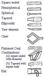
(Reference: Folsom, R.G. (1955). “Review of the Pitot Tube”, University of Michigan Industry Program of the College of Engineering. pg. 36.)
Usage Examples
Pitot tubes, such as the one below, are used extensively to measure pressure (or air velocity ) of aircrafts. Various designs are available, depending on aircraft specifications.
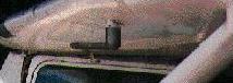
The pitot tube from NASA’s X-31 fighter jet is shown below. The jet travels at almost 1,000 mph with an altitude of 40,000 ft, whereas other aircraft only travel at around 250-500 mph.
Advantages
- Suitable for moving fluid
- Measures both static and dynamic pressure
Disadvantages
- Must be placed in the direction of fluid flow, otherwise measurements will be in error
Bourdon Gauge
Simplicity and small size makes the bourdon gauge a popular pressure measuring device.
General Information
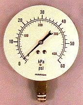
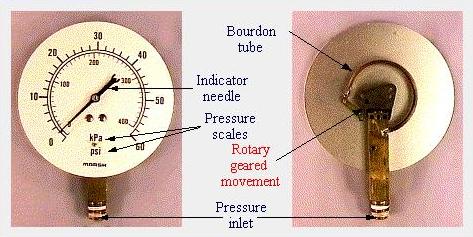
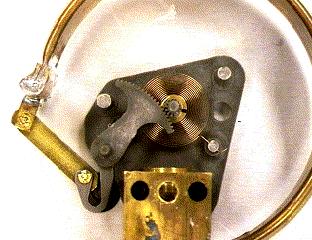
The bourdon pressure gauge is very common and probably the most recognizable piece of pressure measuring equipment. Below are two views of a Bourdon gauge after it has been taken out of its casing.
Equipment Design
When fluid enters the shaft, it travels up into the hollow curved bourdon tube. The pressure of the fluid forces the tube to straighten, turning the gears and moving the needle. Pictured below on the right is a close up of the gear mechanism.
Usage Examples
The bourdon gauge is the most common pressure equipment because it allows for a wide range of pressure measurements. Notice the many uses of the bourdon gauge on these processes.
Advantages
- Can be used for a wide range or pressures, from 0 to 7000 atm
- Can be used instead of manometers at extreme pressures and temperatures
Disadvantages
- Measurement of pressure at high temperatures may cause deformation in the gauge, resulting in systematic errors
Electronic
Strain Gauge
General Information/Equipment Design
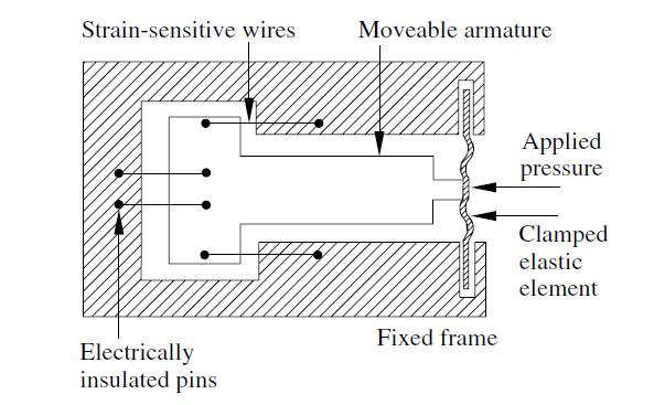
There are two types of strain gauges: unbonded and bonded. The unbonded strain gauge consists of two wires connected to a fixed frame and two wires connected to a movable armature.
When pressure is applied to the diaphragm , the armature moves, and two wires stretch while the other two contract. The resulting change in electrical resistance reflects the pressure applied.
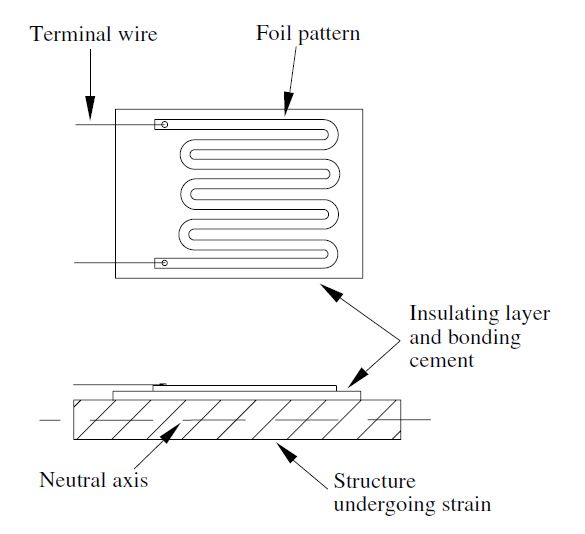
In bonded strain gauges, on the other hand, the wire filament is embedded in cloth, paper, plastic, or resin and is mounted onto a flexible plate, as shown above. When pressure is applied to the flexible plate, the filament wires stretch or contract. The resulting change in resistance reflects the pressure applied.
Usage Examples
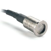
Micro-machined silicon pressure sensors with strain gauges can be used in precision pressure transmitters such as the one below. The gauges are isolated from the pressure source by an external diaphragm. Pressure is transmitted through silicon oil located between the diaphragm and the sensor. Digitization of Data is nothing new; however, getting data from a pressure transmitting device in a usable format can get tricky. Modern innovations have allowed real time data capture, providing room for greater improvement in efficiency and reliability. Smart features that allow for such innovation include ethernet cables to connect the devices to export data straight to a monitoring system, predictable maintenance based on the output of continuous pressure data, and faster response times to alert faulty equipment.
Capacitance
General Information
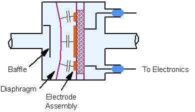
Capacitors are composed of two parallel conducting plates, carrying the same and opposite charge. In a capacitance diaphragm gauge, one or both plates are diaphragms. When pressurized, the diaphragm deflects and changes the dielectric thickness, as shown below on the right.
(Courtesy of MKS Instruments, Andover, MA)
Equipment Design
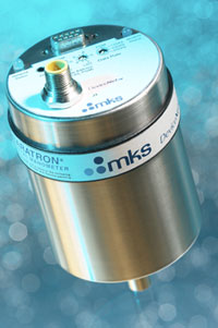
Capacitance diaphragm gauges with two diaphragms as their pressure sensor can be used to measure differential pressure, in applications with two pressure sources. The diagram below depicts a capacitance manometer that acts as a stand-alone transducer. It measures the pressure by sending a signal from 0-10 volts that is directly proportional to the pressure.
Usage Examples
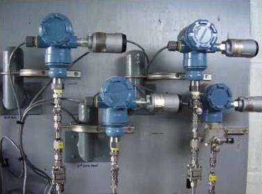
The picture below shows four capacitance manometers that were used to monitor the outlet gas pressures from four district regulators.
Potentiometer
General Information
A potentiometer is a variable resistor composed of a resistor connected to a circuit and a contact. In a potentiometer pressure transducer, the potentiometer is connected to an elastic element which is exposed to pressure.
When pressure is applied, the element flattens, causing the contact to move over the resistor, changing its resistance. This change can be measured by a voltmeter.
Piezoelectric Elements
General Information
When piezoelectric crystals are stressed in a particular direction, a separation of charge occurs on the surface, which reflects the amount of pressure applied to it. Common piezoelectric elements include quartz, tourmaline, Rochelle salt, barium-titanate, and lead-zirconate-titanate.
Piezoelectric materials are used to measure pressure in explosives, internal combustion engines, vibrations, accelerations, and impacts that are virtually impossible to measure with other devices.
Piezoelectric elements can come in a variety of shapes in sizes, but the most common are discs, rings, plates, and cylinders .
Linear Variable Differential Transformer sensor (LVDTs)
General Information
Linear Variable Differential Transformers (LVDTs) consist of a magnetic core, an elastic element such as a diaphragm, and one primary and two secondary coils. Voltage is applied to the primary coil to produce a magnetic field. When the core is centered, the induced voltages in the secondary coils are equal and opposite.
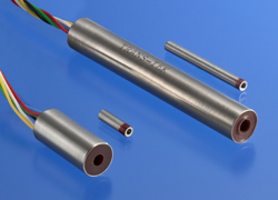
When pressure is applied to the system, the diaphragm moves, shifting the magnetic core and inducing a voltage in one secondary coil and decreasing the voltage in the other. This voltage difference is linearly proportional to pressure and can be measured accordingly.
Variable Reluctance
General Information
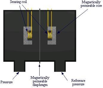
Variable reluctance pressure transducers are composed of two magnetic coils connected in series and a flat magnetic diaphragm .
When pressure is applied to the system, the diaphragm deflects, changing the magnetic field in both coils, which induces a current. The current can then be measured with an ammeter or other equipment.
Acknowledgements
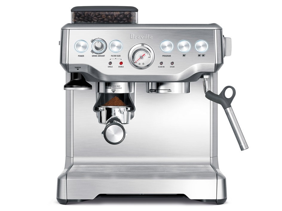
- Breville USA
- Emerson Process Management, Chanhassen, MN
- MKS Instruments, Andover, MA
- NASA-Dryden, Edwards, CA
- TRANS-TEK, Inc., Ellington, CT
- W.A. Baum Co. Inc., Copiague, NY
- University of Michigan, Department of Chemical Engineering, Ann Arbor MI
- U.S. Environmental Protection Agency, Seattle, WA
- U.S. Geological Survey
References
- Benedict, Robert P. Fundamentals of Temperature, Pressure, and Flow Measurements . 3rd ed. New York: John Wiley & Sons, 1984.
- Folsom, R. G. Review of the Pitot Tube . Ann Arbor, MI: University of Michigan, 1955.
- LePree, J. (2018, January). Pressure Measurement Gets Rugged, Goes Digital. Chemical Engineering Essentials for the CPI Professional, 11-14. Print.
- Perry, Robert H. and Green, Don W., Perry’s Chemical Engineers’ Handbook . 7th ed. New York: McGraw-Hill, 1997: 10-8 – 10-9, 10-11 – 10-12.
- Thomas, Allan M. Drawings of Micrometer U-tube Manometers For Ranges Up To 100 mm of Mercury . Washington: Government Printing Office, 1967.
- Todd, Carl D. The Potentiometer Handbook . New York: McGraw-Hill Inc. 1975.
Developers
- Sam Catalano
- Brad Lintner
- Blia Kue
- Chris Seadeek
- Steve Wesorick
- Joseph Palazzolo
- Christy Charlton
- Henry Chen
- Austin Potter