Pumps are used to transfer energy to an incoming fluid. The pressure or velocity of the fluid increases, which helps the fluid overcome physical barriers such as pipe friction and height changes. Pumps exist in a variety of shapes and sizes, depending on their intended function. When the flowing fluid is a gas, the pump is typically referred to as a compressor.
Centrifugal
Centrifugal pumps use the rotation of one or more impellers to move fluid. They are ideal for liquids that contain suspended solids and high flow rates.
General Information
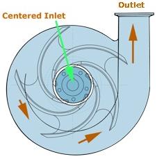
Centrifugal pumps have a single input and output, as shown here. Fluid is fed into the side inlet. A pressure change created by the impeller moves the fluid from the inlet to the outlet.
Centrifugal pumps can have more than one stage. The number of stages determines how many impellers are present in the pump.
Equipment Design
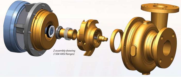
A centrifugal pump adds pressure to a liquid by transferring the mechanical energy of the rotating impeller to the flowing fluid as kinetic energy.
The schematic shown on the left and the exploded view shown on the right display common features of a centrifugal pump.
Pumps are designed to operate within a range of pressures and temperatures. Centrifugal pumps produce heat, which causes liquid expansion and possible vaporization, leading to excessive pressure. These pumps are protected from over-pressurization using a pressure relief valve or a rupture disk.
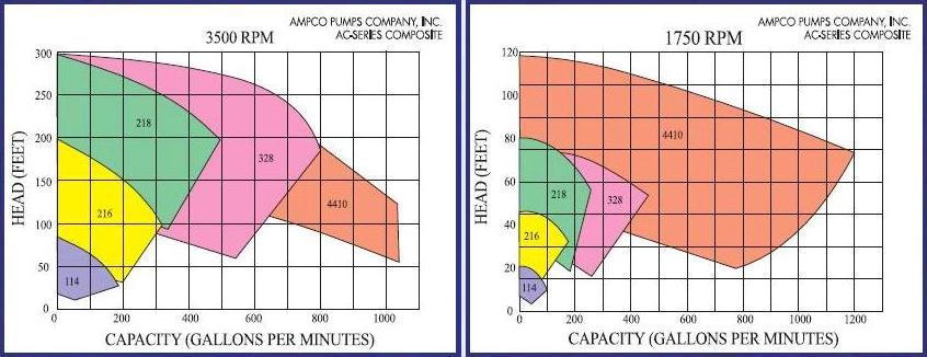
The performance curves below show the capacity and pressure range of operation for five centrifugal pumps.
Operating a pump outside of the proper pressure and temperature range could result in cavitation : The liquid flowing into the inlet starts to vaporize due to the vacuum conditions. The liquid-vapor feed travels through the pump, and the pressure increases upon reaching the outlet, causing the vapor to condense. Cavitation can also cause pressure variation, shaft deflection, vibrations or mechanical shocks that will damage the pump seals. This process is explosive and causes great wear to the pump components, especially the rotor. Proper design of supply vessels and suction-piping systems can help avoid these problems.
Usage Examples
Centrifugal pumps are used in the construction industry as a sump pump to remove water from ditches, streams, and basements. They are also used extensively for industrial applications. Some industries include steel, paper, oil, appliance, and wine. These pumps can handle everything from clear liquids to corrosive slurries.
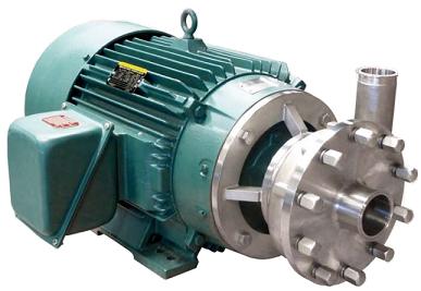
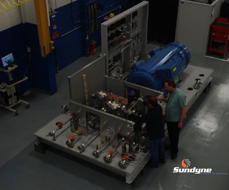
Centrifugal pumps are specially designed to handle large solids without jamming. A cover plate allows for easy access to the pump interior if clogging occurs. They are best suited for liquids with low viscosities (0-500 cP) and large flow rates (40-1,500 gallons per minute). This large volume capacity is needed for a variety of functions, such as providing clean water to the plant, removing wastewater, and transferring water from settling ponds to lagoons. The centrifugal pump pictured below is used in freshwater feed applications in refineries.
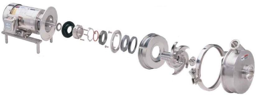
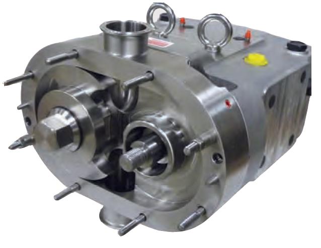
Centrifugal pumps can be customized for applications in which cleanliness is important, such as in the food industry. The circular casing, open impeller, and volute backplate in the pump pictured below are made of 316 stainless steel with smooth radii for easy cleaning. In addition, all steel components are accessible for cleaning and can be sterilized without disassembly.
Advantages
- Steady delivery – uniform flow.
- Can handle all types of fluids.
- Can be mounted horizontally or vertically.
- Relatively low cost.
- High cleanability.
Disadvantages
- Reduced performance when handling viscous fluids.
- Can only handle small amounts of gases in liquids.
- Not effective for high-pressure applications: Single-stage pumps require high velocities, but multi-stage configurations are expensive.
- Priming is often needed before start-up.
Positive-Displacement Reciprocating
Most non-centrifugal pumps are positive-displacement pumps. These can be further categorized depending on the method used to fill and empty the pump cavity. This section explores a reciprocating action.
(Copyright Flowserve Corporation, Irving, TX)
General Information
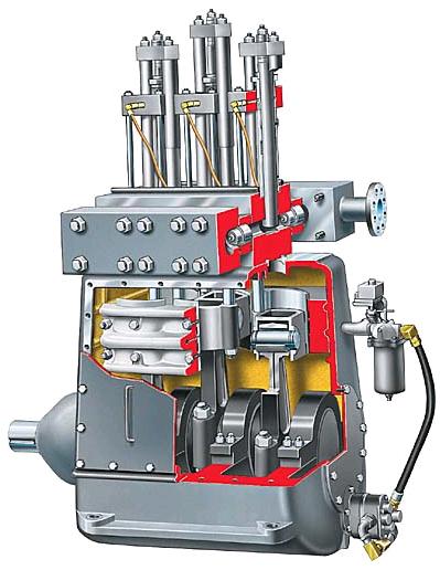
In positive-displacement reciprocating pumps, fluid is pumped by a plunger traveling back and forth in a chamber. Valves for intake and discharge operate in conjunction with the plunger to transfer the fluid.
Equipment Design
In reciprocating pumps, fluid is transferred by the motion of either a piston or plunger moving in a cylinder or by the flexing of a diaphragm. The Piston movement is described below.
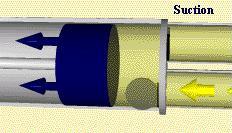
On the suction stroke, the volume of the pump cavity increases, lowering the pressure inside the cavity. This causes the suction valve to open, allowing the fluid to flow into the cavity. At the same time, the discharge valve is closed, preventing backflow.
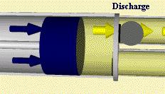
On the discharge stroke, the volume of the pump cavity decreases, causing the pressure inside the cavity to increase. This increased pressure closes the suction valve and opens the discharge valve, forcing the fluid out of the pump.
Reciprocating pumps can be optimized to provide a constant flow rate. In this example, compressed air is directed through an air valve into the left chamber, and then into the right chamber. The reciprocating motion of the two flexible diaphragms creates an action that automatically provides an alternating suction and discharge in each chamber. This force moves the liquid from the inlet to the outlet of the pump. Valves in the inlet and outlet piping control the intake and discharge flow through the diaphragm chamber. These pumps can be driven mechanically, hydraulically, or electrically.
Usage Examples
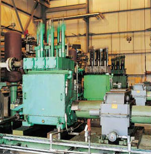
Reciprocating pumps are often used in the food industry. In sugar factories, piston pumps are used to pump carbonation slurry. They are also used in the construction industry to help pour concrete foundations, as the picture below demonstrates.

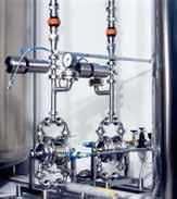
Diaphragm pumps are often used as metering pumps because they provide precise dosing. The number of process materials being transported can be measured, and stroke volumes or stroke frequencies adjusted to modify or correct the flow rate. Occasionally, other types of positive-displacement reciprocating pumps are also used for this duty. Diaphragm pumps are typically used for solid-containing slurries, often in the food industry.
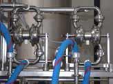
The double diaphragm pumps shown below to the left are used in a hair color additives production process, and the ones to the right are used to transfer fruit juice concentrate.
(Copyright Granzow Inc., Charlotte, NC)
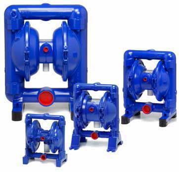
The air-operated double diaphragm pumps shown below have applications in ceramics manufacturing, spray painting systems, and mining operations.
Advantages
- Can handle volatile and very viscous liquids.
- Adjustable capacities for improved metering.
- Able to produce very high pressures.
- Diaphragm pumps are leak-free and do not expose packing or seals to the process liquid.
- No priming is typically needed.
Disadvantages
- Reactor temperature is difficult to control.
- Produces a pulsating flow, and operates at low speeds.
- Limited range of capabilities.
- High net positive suction head (NOSH) requirements.
- Much maintenance required
Positive-Displacement Rotary
Most non-centrifugal pumps are positive-displacement pumps. In this section, those that use a rotor will be examined.
General Information
There are two types of rotary pumps: gear and screw. They both operate in the same way, except that the screw pump contains a modified gear.
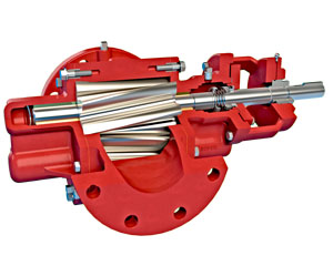
Shown below is a bi-wing gear pump. The rotation of these wings displaces the liquid and pushes it from the inlet to the outlet.
Equipment Design
In rotary gear pumps, lobes rotate inside the casing with very little clearance. The bi-wing design is becoming increasingly popular because it causes less shear due to minimal rotor-to-rotor contact. Bi-wing rotors also handle solids and delicate products more efficiently than 3-lobe rotors because of the large cavities formed between the rotors.
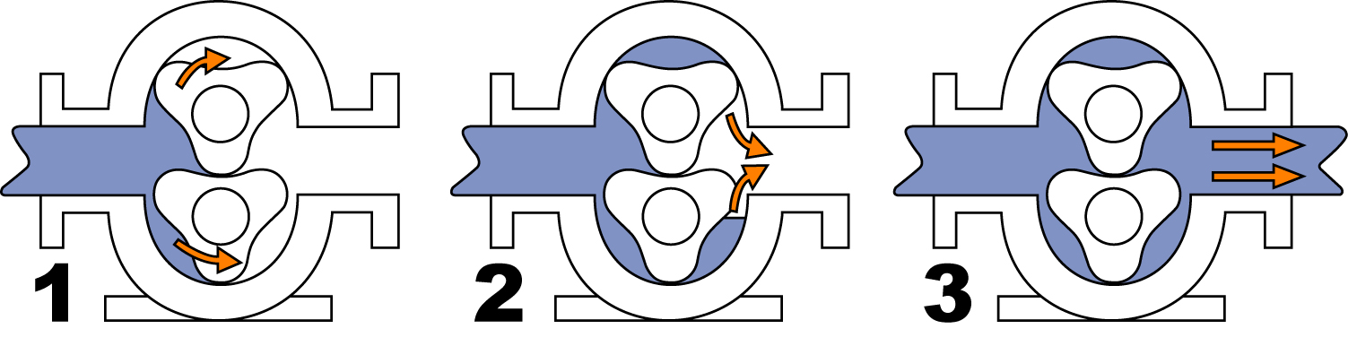
The animation below demonstrates fluid motion through a bi-wing rotary gear pump. The fluid enters the spaces between the lobes as they pass the inlet, and then it is carried around and forced out of the outlet.
The internal components of a bi-wing rotor pump are shown below in the cutaway diagram.
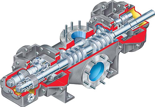
Below is an example of a screw rotor pump. A helical rotor rotates inside a double helix stator without any clearance. As it rotates, cavities form that channel the flow to the outlet.
Usage Examples
Rotary pumps are used in several industries including food, chemical, pharmaceutical, pulp/paper, and cosmetics. Bacteria-free operation is vital in the food and pharmaceutical industries to ensure freshness, flavor, color, and shelf life. This gear pump is used in industries in which sanitation is important, including beverage, dairy, candy, canned food, cosmetics, and meat industries. In the petroleum industry, gear pumps are used to transport both crude and refined products.
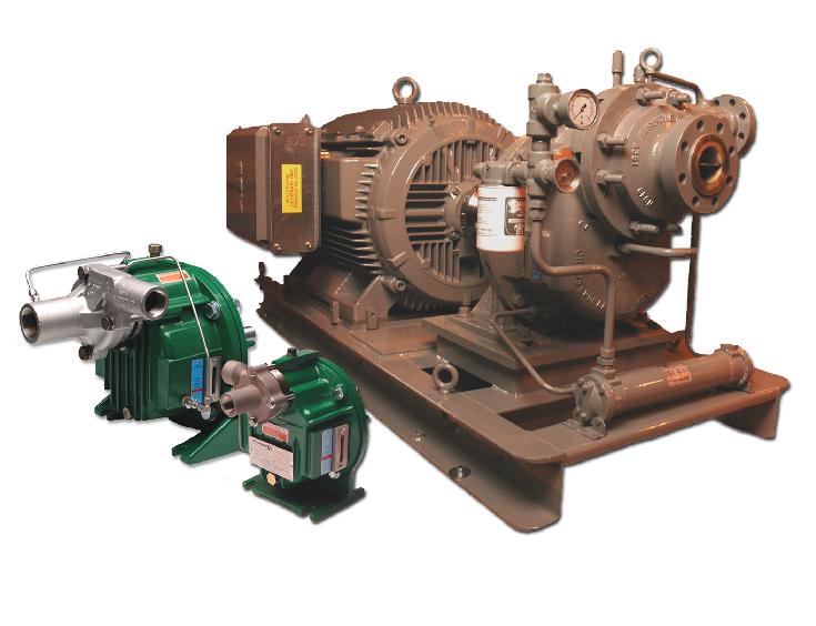
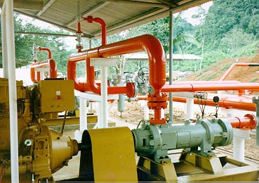
Gear pumps have two or more impellers inside the casing that rotates with an extremely small clearance between them. The one shown below is used in a variety of applications within the chemical processing and petroleum refinery industries.
The screw pump below is used to recover crude oil trapped deep in the ground. The collected crude is very thick and contains solid particles such as sand and silica.
Advantages
- Handles highly viscous fluids well.
- Able to handle fluids that are corrosive, edible, or contain entrained gases.
- Quick and easy cleaning.
- Works well for liquids with low vapor pressures.
- Compatible with many materials
Disadvantages
- Does not produce high pressures as well as reciprocating pumps.
- Practical sizes are more restricted than in centrifugal pumps.
Rotary Lobe
Rotary lobe pumps operate similarly to gear pumps. As in rotary gear pumps, fluid flows around the interior of the casing, but the rotating lobes do not make contact. The large pumping chamber allows lobe pumps to handle solids, slurries, and pastes.
Equipment Design
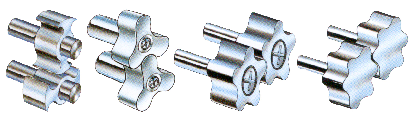
The picture below demonstrates the variety of lobe options available, which include single lobe, bi-wing, tri-lobe, and multi-lobe. The bi-wing design is becoming increasingly popular because it causes less shear and has larger cavities that allow it to handle solids and delicate materials better than tri-lobe rotors. A gearbox with timing gears is used to prevent lobe-to-lobe contact.
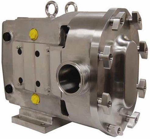
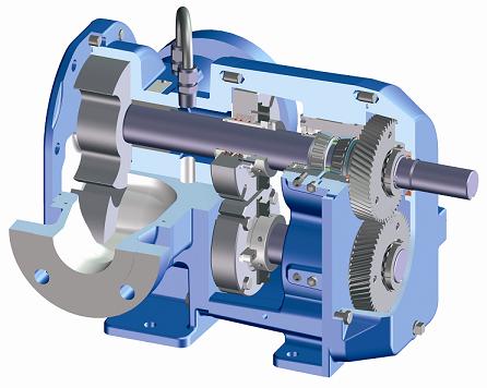
The cutaway picture below shows the internal components of a bi-wing rotary lobe pump.

Usage Examples
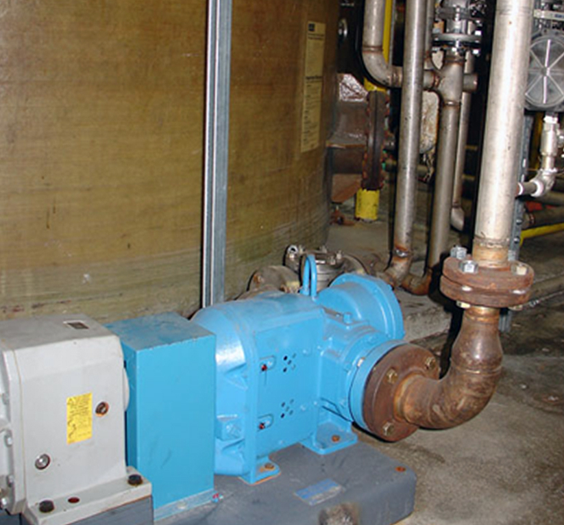
Lobe pumps are often used in the food industry because they can handle solids without damaging the food. They can be used for many other applications, including polymers, paper coatings, soaps, paints and dyes, rubber, adhesives, and pharmaceuticals. Pictured below is a lobe pump used in soap production.
Advantages
- No metal-to-metal contact.
- Handles solids and delicate materials.
- Can operate dry for long periods of time.
Disadvantages
- Requires timing gears.
- Requires two seals.
Turbine
General Information
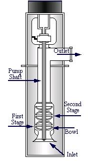
In turbine pumps, the liquid enters through the bottom, is pushed by the impellers toward the outside of the bowl, and is then sucked up through the outlet.
Turbine pumps typically have multiple stages requiring multiple impellers to increase capacity. They are often referred to as diffusion pumps and are classified as centrifugal pumps
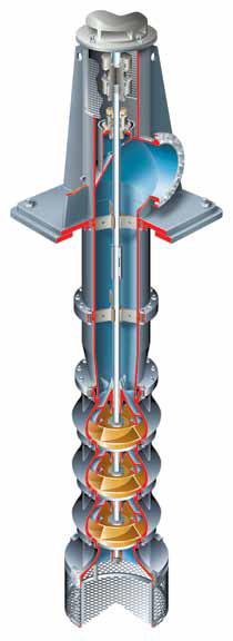
(Copyright Flowserve Corporation, Irving, TX)
Usage Examples
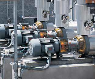
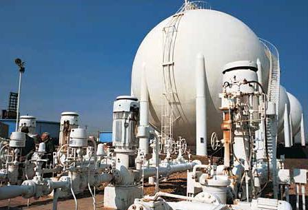
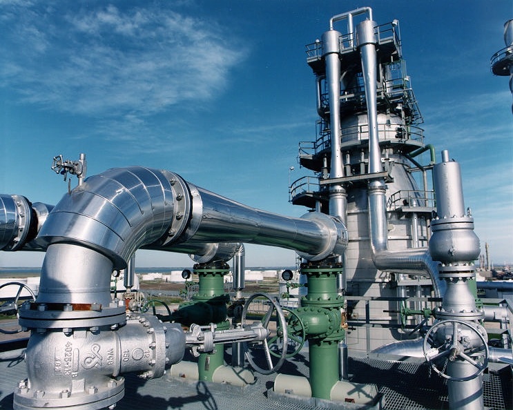
Turbine pumps are usually used for water circulation, oil processing in refineries, and large volume drainage. The turbine pumps in the picture below are used in the oil and gas industry.
Advantages
- Transports high volumes in a short time
- Only one moving part
- Quiet
Disadvantages
- Power intake increases rapidly with decreasing flowrate
- Sensitive to dirt
Ejectors
Ejectors use steam or air to pump gases, liquids, and granular solids.
General Information
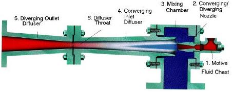
The movie below shows the basic operation of an ejector. High-velocity jets of steam, shown in yellow, entrain gases, liquids, or granular solids, shown in blue, and deliver them to a region at higher pressure. The compressed mixture, shown in green, flows through the outlet diffuser.
Equipment Design
Below is a schematic showing the operation of an ejector. During operation, atmospheric- to high-pressure steam travels through a motive fluid chamber and into a converging/diverging nozzle. After it exits the mouth of the nozzle, the steam pressure is lowered as it accelerates to high velocity and entrains the suction fluid. The two streams mix in the mixing chamber and pass into the converging inlet diffuser. The mixed stream passes through the diffuser throat and is compressed, then exits through the diverging outlet diffuser. The final discharge pressure is normally 5 to 15 times the suction pressure.
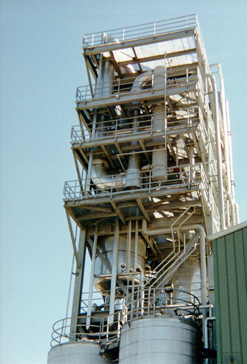
Ejectors can be operated as a single-stage or as multiple stages. A single-stage ejector can pump gases, liquids, or solids to pressures twelve or more times the inlet pressure. The picture below shows a five-stage ejector for a polyester plant. By combining ejectors in series, a larger range of pressure changes is possible.
Instead of using steam as the working fluid, compressed air can also be used. Using high-pressured air was often overlooked in the past because of the high costs involved in compressing air and the technology was not readily available. With improvements in air compression technology, it can be cheaper to feed compressed air to get the same effects as a steam ejector.
Since air cannot be compressed under normal temperatures and pressures the way that steam can, air ejectors can only be used for systems up to three stages. A steam ejector would prove to be more economical in cases where steam is more accessible at the plant and many stages are needed.
Usage Examples
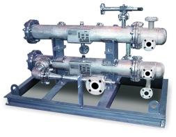
The air ejectors pictured below can be used to pump corrosive, tarry, or sludge liquids.
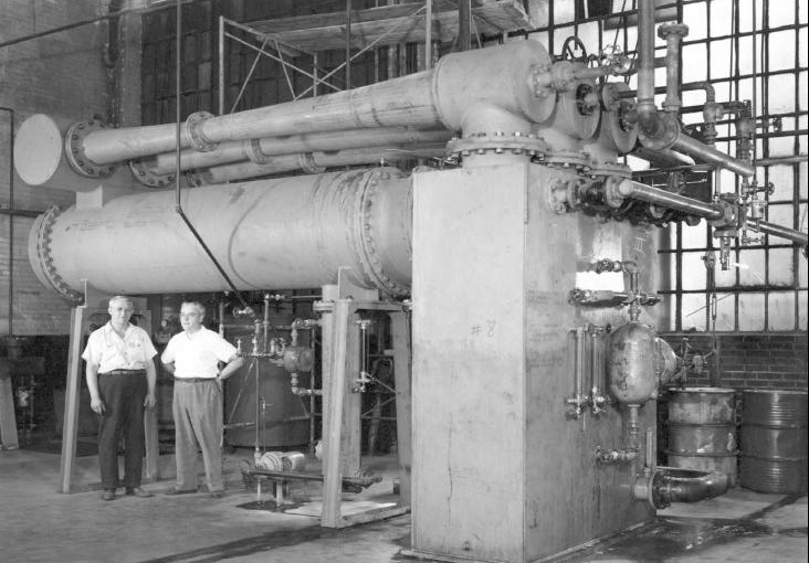
Ejectors are used in highly corrosive environments. The ejectors shown below are used in a refining process. Ejectors are also commonly used in compression refrigeration systems.
Advantages
- Highly reliable.
- Low initial cost.
- The simplicity of operation.
- Lack of moving parts.
- Made from a wide variety of metals and moderate-strength erosion-resistant nonmetals
- Can be used to pump highly corrosive and/or abrasive materials.
- Smooth, open flow passages allow handling of entrained solids and liquid slugs without damage.
Disadvantages
- Not energy efficient.
- Limited ability to handle air overloads.
- Contact between steam and process vapors may cause process and environmental contamination.
Acknowledgements
- Ampco Pumps Company, Glendale, WI
- Colfax Fluid Handling, Fulton‚ MD
- Expert Process Systems, Hackettstown, NJ
- Flowserve Corporation, Irving, TX
- Gardner Denver Nash, Charleroi, PA
- Graham Corporation, Batavia, NY
- Granzow Inc., Charlotte, NC
- Roper Pump Company, Commerce, GA
- Schwing America, Inc., St. Paul, MN
- Viking Pump, Inc., a unit of IDEX Corporation, Cedar Falls, IA
References
- American Institute of Chemical Engineers. American Institute of Chemical Engineers’ Pump Manual . New York: 1960. Print.
- Cheremisinoff, Nicholas P. and Paul N. Cheremisinoff. Pumps and Pumping Operations. Englewood Cliffs, NJ: Prentice-Hall Inc., 1992. Print.
- Croll, Samuel W. “Keeping Steam Ejectors On-line”. Chemical Engineering April 1998: 108-112. Print.
- Dicmas, John L. Vertical Turbine, Mixed Flow & Propeller Pumps . New York: Mc-Graw Hill, Inc., 1987. Print.
- Grossel, Stanley S. “Pump Hazardous Liquids Safely.” Chemical Engineering February 2008: 38-39. Print.
- Holland, F. A. and F. S. Chapman. Pumping of Liquids. New York: Reinhold Publishing Corporation, 1966. Print.
- Karrassik, Igor J. Centrifugal Pumps. 2nd ed. New York: Chapman & Hall, 1988.
- Perry, Robert H. and Green, Don W., Perry’s Chemical Engineers’ Handbook . 7th ed. New York: McGraw-Hill, 1997: 10-24 – 10-29, 10-31 – 10-35, 10-56 – 10-57, 11-90. Print.
- Power, Robert B. Steam Jet Ejectors for the Process Industries New York: McGraw-Hill Inc., 1994. Print.
- Roper, Daniel L., and Ryans, James L. Process Vacuum System Design & Operation. New York: McGraw-Hill Book Company, 1986: 229-260. Print.
- Roth, A. Vacuum Technology . Elsevier Science Publishing Co. Inc., 1990: 222. Print.
- Schiavello, Bruno, and Frank C. Visser. Pump Cavitaion– Various NPSHR Criteria, NPSHA Margins, and Impeller Life Expectancy. N.p.: n.p., 2009. 114. Web. 15 Aug. 2012.
- Smith, Bruce. “What Makes a Pump For High-Purity Fluids?” Chemical Engineering April 2002: 87-89. Print.
- Wahren, Uno. Practical Introduction to Pumping Technology . Houston: Gulf Publishing Company, 1997. Print.
- Wilkes, James O. Fluid Mechanics for Chemical Engineers. 2nd ed. Upper Saddle River, NJ: Pearson Education, Inc., 2006. 188-89. Print.
Developers
- Mike Africa
- Janet Mihalyfi
- Mark Colosimo
- Melissa Schlosser
- Julie Messacar
- Steve Wesorick
- Matt Robertson
- Abigail Nalbandian
- Kelsey Kaplan
- Steve Cotton
- Austin Potter