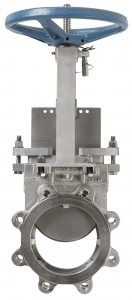
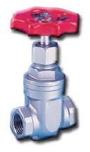
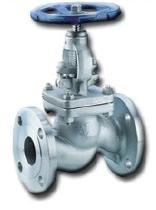
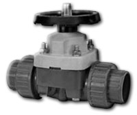
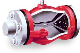
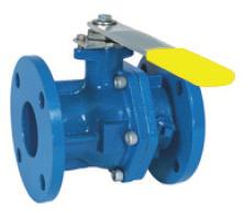
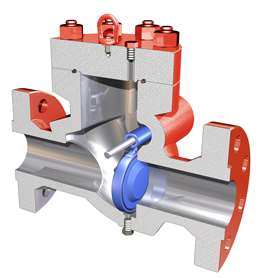
Valves regulate the flow of fluids and isolate piping or equipment for maintenance without interrupting the other connected units. They are typically controlled with actuators; use of manual valves may create safety problems in emergency situations. The valves below are categorized according to the system used by Valve Manufacturers Association of America. They categorize valves into four main types: Linear motion valves, Rotary valves, Self-actuated valves, and Specialty valves
Linear Motion Valves
Linear motion valves include any valve that closes by the linear sliding motion of a structure within the valve. These include gate, globe, diaphragm, pinch, and needle valves.
Gate
Gate valves are primarily used for on/off applications. They are not used to regulate flow.
General Information
Gate valves are very common due to their simple design and ease of operation. The gate is raised by a threaded stem to allow fluid flow. Gate valves are not recommended for throttling or restricting fluid flow by having the valve partially open.
Equipment Design
Gate valves are very simple and operate in either the fully open or fully closed position. By turning the handle on the top, the screw turns and moves the wedge up or down. The wedge is angled so that if wear does occur, the wedge will still be guided into position. When a gate valve is fully open, there is a very small pressure drop across the valve. Conversely, when the valve is fully closed, it is pressurized and very well sealed. With the appropriate mating of a disk to seal the ring, very little or no leakage occurs across the disk when the gate valve is closed. Gate valves open and close very slowly to prevent fluid hammers and consequent damage to the piping system.
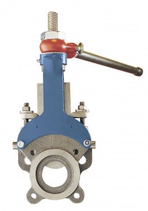
A slide gate valve is a special kind of gate valve. When the handle is turned, the threaded screw turns, lifting the plate that shuts off the flow, as shown in the picture below. Slide gate valves are fairly common and used in many industries.
Usage Examples
Gate valves are found in a variety of industries, such as underground water or sewage disposal applications. They are also commonly found in irrigation and distribution service lines.
Gate valves are suited for high pressures and temperatures and are also used for low-pressure steam, and non-corrosive gas or oil.
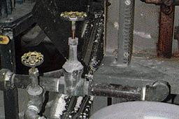
The picture below shows two gate valves used in a filtration process.
Advantages
- Suitable for high temperature and high-pressure situations.
- Low-pressure drop when fully open.
- Tight seal when fully closed.
- Relatively free of buildup.
- Low leakage, low maintenance, and little noise.
Disadvantages
- Slow response times require large actuator forces.
- Prone to vibration when the valve is partially open.
- Subject to erosion from the high-velocity flow that occurs when the gate is opened, which eventually prevents tight shutoff.
Globe
Globe valves are the most common type of valves for regulating flow. The picture below shows a typical globe valve.
General Information
Globe valves are primarily used for throttling purposes. They are also ideal for situations in which operation is frequent or tight shutoff is desired.
In the pictures below, fluid flows from left to right. The change in elevation within the valve results in high flow resistance and turbulence, and a large pressure drop. Globe valves can only regulate flow in one direction, whereas gate valves can regulate flow in both directions.
Equipment Design
Because globe valves operate with a perpendicular movement of the disk toward or away from the seat ring, the annular space between the seat and the disk close gradually as the valve closes. As a result, globe valves are ideal for throttling purposes and situations in which operation is frequent or tight shutoff is desired.
The plug can be raised or lowered a specific amount to allow fluid to flow at a given rate. The disk-to-seat-ring contact is very close to forming right angles, which allows the force of closing to tightly seat the disk. At this point, the plug will just move further down, and there will still be a tight seal. When the valve is closed, there is no blocked-in volume. As a result, globe valves tend to have very little or no leakage around the seat.
In single-seated globe valves, the most common type of globe valve, the plug is only guided from the top part of the valve. In double-seated globe valves, the plug is guided from the top and bottom.
High volume noises are created because of the high pressures and large pressure drops through the valves when the valves do not use a technique known as jet independence to break up the noise. Jet independence helps alleviate the noise: small holes drilled on the sides of the valve’s cages, shown below, allow small streams to flow through, breaking up the sounds into higher frequency sounds that can be easily dissipated. There are three styles of holes that provide up to 40 dB(A) of noise reduction.
Globe valves can have digital controllers attached to them to control the operating position and the health of the valve. These controllers can identify issues such as low/dirty air supply, incorrect regulator setting, air leak, stuck valve, excessive friction, or a broken spring. Controllers now offer wireless valve monitoring to make monitoring many valves simple.
Usage Examples
Globe valves are used in many applications which regulate flow. The two globe valves shown below are being used to regulate the flow of water in a filtration process.
Advantages
- Efficient throttling with minimal damage to the valve.
- Large number of design options.
- A pneumatic diaphragm actuator and control system can be added for precise throttling.
Disadvantages
- Highest pressure drops of all valves.
- Requires a lot of force to open or close the valve.
- Expensive.
Diaphragm
Diaphragm valves are excellent for regulating flow. Turning the wheel of a diaphragm valve will change the flow of the passing fluid.
General Information
When the wheel of a diaphragm valve is turned, it turns a screw that forces the diaphragm to decrease the incoming fluid flow rate. The diaphragm is the only part of the valve that is exposed to the fluid, minimizing erosion effects. The flow passing through the diaphragm is unobstructed by moving parts and free of crevices.
Some diaphragm valves have a spring instead of a screw. This spring holds the valve in the closed position until the fluid pressure becomes large enough to counteract the spring. Large fluid pressures will force the diaphragm into the open position.
Equipment Design
Two general designs exist, straightway and weir. In straightway valves, the pipe is completely straight. This design does not obstruct fluid flow and, hence, it is well suited for slurry and higher-flow applications. The picture shown below is a typical weir-style diaphragm valve, in which the two pipes bend up toward the center of the valve. This design is used for higher pressure applications. Both types of diaphragm valves are excellent in providing tight shutoff.
The diaphragms can be made from a wide variety of materials including natural rubber, synthetic rubber, or Teflon®. The picture below shows several rubber diaphragms. The diaphragms are inexpensive and easy to replace, so maintenance is inexpensive, quick, and easy.
The life of a diaphragm varies greatly depending on the temperature, pressure, and frequency of opening and closing in each situation.
Usage Examples
Diaphragm valves are used in a wide variety of industries including mining, water treatment, and food processing. Diaphragm valves are commonly used in applications where cleanliness, bubble-tight shutoff, and chemical compatibility are important since the fluid inside the diaphragm is free of gaps and moving parts. Diaphragm valves are considered to cause the least contamination and are often used in high purity applications.
Advantages
- Excellent for fluids containing suspended solids.
- Maintenance is inexpensive and not required often, given the long life of the diaphragm.
- Will not contaminate the fluid, and the fluid doesn’t damage the valve.
Disadvantages
- Limited to pressures of approximately 50 psi.
- Limited to temperatures below 180°F.
- Has bad flow characteristics, requires high and varying force to close the valve.
Pinch
Pinch valves are excellent at regulating flow and have a wide variety of uses.
General Information
A pinch valve contains a flexible tube that may be pinched to constrict the fluid flow. Pinch valves may be used to throttle or restrict fluid flow. Pinch valves may also be used to turn fluid flow completely off.
Equipment Design
Pinching is accomplished by applying pressure to the flexible portion of the valve. This may be accomplished mechanically or can be accomplished by the exertion of fluid pressure.
Mechanical Fluid pressure controlled
Much the like diaphragm in the diaphragm valve above, the flexible portion of the pinch valve body is made of elastomers, natural rubber, or synthetic rubber. Often times the flexible portion is made up of a combination of fabric and elastomers to increase mechanical strength. The flexible portion is referred to as the valve sleeve. The sleeve can easily be detached and replaced.
Usage Examples
While the pinch valve provides a tight seal, the sleeve material is soft, so the valve can seal around solids without damaging them. Pinch valves are therefore well suited for slurries and fluids with suspended solids. Industries that use this technology of pinching flow without damaging solids include pharmaceuticals and food handling.
Advantages
- Excellent for fluids containing suspended solids.
- Maintenance is inexpensive and not required often, given the long life of the valve.
- Will not contaminate the fluid, widely used in FDA regulated processes for this reason.
Disadvantages
- Limited to pressure and temperature capabilities of the sleeve material.
- Fluid pressure-operated pinch valves cannot run under vacuum conditions.
- Pinch valves should always start open when starting a pump upstream.
- May fail if flow pulsates
- If used as the main shut-off of flow in a liquid system, the valve pressure must be watched because the pressure will eventually exceed the valve’s capacity. If this is the case then the valve will burst.
Needle
Needle valves are excellent for precise flow regulation at low pressures.
Company © 2014)
General Information
Needle valves can handle a large range of flow conditions including liquid systems, gas systems, systems with solids suspended in the fluid, and vacuum conditions. Needle valves are most commonly used for controlling flow when precise and minute changes in flow rate are required.
Equipment Design
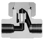
The valve itself consists of a spindle and a needle. The spindle is at the top and is turned to raise or lower the needle. The needle is a long rod with a cone-shaped tip. When fluid is flowing through the valve, the entering fluid turns 90° and passes through an orifice, or void, created by the cone-shaped tip of the needle. Moving the needle’s position changes the flow rate by changing the size of the orifice.
Usage Examples
Needle valves perform well when precise throttling is required at low pressure. They are often used in processes where a low, constant flow rate must be maintained. Examples of such processes include filling a vacuum tube, or in a process involving a carburetor. A carburetor is a device that combines and mixes two fluids, usually air and fuel, into an internal combustion engine.
Advantages
- Performs well a low pressure.
- Performs well with system fluids that are gas, liquid, cryogenic, or fluids with suspended solids.
- Can throttle to make small and precise adjustments in flow rate.
- Can be used under vacuum conditions.
Disadvantages
- Takes a long time to fully close and fully open. Also takes a long time to change the flow rate by a large amount.
- Does not perform well under high flow rates.
- Easily damageable by large changes in system flow rate or system pressure.
Rotary Valves
Rotary valves include any valve that closes by the rotational, spinning motion of a structure within the valve. These include ball, plug, and butterfly valves.
Ball
Ball valves are the most common and versatile type of rotary valves. A typical ball valve is pictured below.
General Information
The rotary valves pictured below use a ball-shaped disk with a hole bored through to stop or start fluid flow. By turning the handle a quarter turn, the valve is turned to either the opened or closed position. When the valve is opened, the ball is rotated so that the hole is aligned with the valve’s body’s inlet and outlet. When the valve is closed, the ball is rotated so that the hole is perpendicular to the flow. Ball valves are quick opening and closing and have tight shutoff characteristics.
The ball moves across the seat with a wiping motion. As a result, ball valves can handle fluids that contain suspended solids.
Equipment Design
The picture below shows the major components of a ball valve. When you turn the handle 90°, the ball turns 90°, shutting off the flow.
Ball valves are compact, easy to maintain, and provide good shutoff characteristics.
There are two different ball valve designs. In a free ball valve, the ball is separate from the stem, as shown below on the left. In a fixed ball valve, shown below on the right, the ball is part of the stem. The fixed ball valve requires less force to turn the ball.
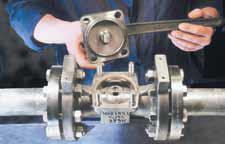
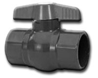
The picture below to the left shows a unique example of how easy it is to take a ball valve apart for cleaning. Some ball valves are made from PVC pipe, as shown below to the right. These pipes are ideal for high corrosion applications, such as handling strong acids.
Usage Examples
Ball valves are manufactured to handle a variety of fluids including corrosive chemicals, viscous liquids, gases, and even acids. The picture below to the left shows a ball valve implemented into a pipeline. Ball valves such as the one pictured below to the right can be used in cryogenic temperatures ranging from -130°F to 32°F.
Advantages
- Highest flow capacities.
- Low-pressure drop and low leakage.
- Rapid opening and relatively contamination-free.
- A pocket ball valve can be used for quick, in-stream sampling.
Disadvantages
- Limited to low temperatures that have little effect on their plastic seats.
- Typically, the entire valve must be removed from the line for maintenance.
- Some fluid may be trapped in the ball in the closed position, damaging the valve.
- Due to rapid opening, surge pressures may arise which could damage equipment downstream.
Plug
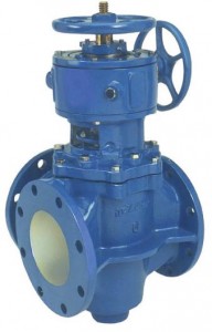
Plug valves are the oldest and simplest type of valve still used in industry. The picture below shows a typical plug valve.
General Information
Plug valves are quick to open and close and they do not leak. Plug valves are very similar to ball valves. Instead of a ball, a rotary cylinder or tapered plug with a hole through it is rotated 90° to allow or prevent flow. Plug valves, like ball valves, are not used for throttling.
Plug valves often have fluorocarbon seating materials and sometimes they are fully lined with fluorocarbon. This provides excellent protection for corrosive applications that require bubble-tight shutoff.
Equipment Design
The schematic below shows the major components of a plug valve. Ball bearings beneath the cylinder reduce friction and provide easier rotation of the plug. Some plug valves have a lubricant beneath the cylinder instead of ball bearings.
Usage Examples
Plug valves are typically found in the gas industry and the wastewater industry. The picture below shows a three-way valve designed for shutoff services. Plug valves are often used in the wastewater industry because they do not allow the buildup of sediments, which could clog the pipes.
There are also several types of plug valves commonly used in Chemical Plant Industries (CPI); these include lubricated, non-lubricated, and eccentric types.
Advantages
- Pressure drop is low.
- High flow capacities.
- Low leakage.
- Rapid opening and relatively contamination-free.
Disadvantages
- Some fluid may be trapped in the cylinder while in the closed position, damaging the valve.
- Due to rapid opening, surge pressures may arise which could damage equipment downstream.
Butterfly
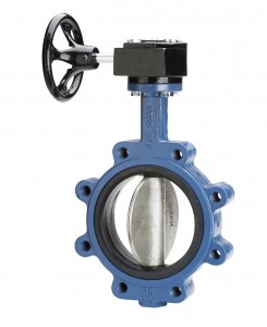
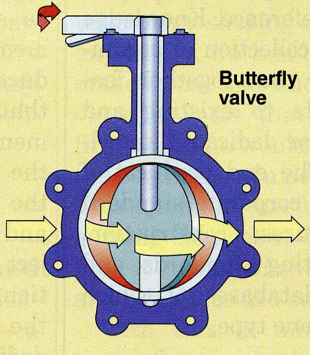
Butterfly valves are the largest type of valve, and they are commonly used for gas and steam control. This picture shows a butterfly valve in the closed position.
General Information
Butterfly valves have a very simple design. They consist of a flow controlling disc that rotates about a shaft that opens and closes at right angles to the flow path. Turning the handle a quarter turn makes the disc rotate to the open position, which allows maximum flow. The picture below shows the direction of the flow when the valve is in the open position.
Equipment Design
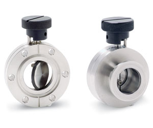
The rotating disc is the same size as the internal diameter of the pipe. Seals are needed to help prevent leaking. The pictures below show a butterfly valve fully open. Notice the disc is parallel to the flow path, allowing for the least pressure drop and maximum flow rate.
Usage Examples
Butterfly valves are typically used in large pipes with diameters greater than 4 inches, and in situations in which some leaking is relatively unimportant. They are applicable for both on/off and throttling applications. The picture below shows butterfly valves that are used as shutoff valves for pump isolation.
Advantages
- Require less space than any other valve.
- Inexpensive.
- Excellent flow characteristics.
- Require a steady amount of force to open/close the valve.
- Very low-pressure drop.
Disadvantages
- Slow response characteristics.
- Require large actuator forces.
- Must be custom-designed for each use.
Self-Actuated Valves
Self-actuated valves include any valve that regulates itself. See for more details. These include check, and pressure relief valves.
Check
There are two main types of check valves, lift and swing. The picture below shows a lift check valve.
General Information
Check valves, such as the one shown below to the right, prevent fluid from flowing through until pressure builds up and forces the valve to open. Check valves allow fluid flow in one preferred direction and prevent backflow, or flow in the opposite direction. These kinds of valves begin to close as the pressure in a pipeline drops and the fluid momentum slows down. When the flow direction reverses, the check valve closes completely.
In the schematic below to the left, the fluid travels from left to right. The gate prevents any backflow from occurring.
Equipment Design
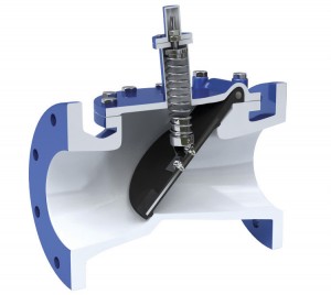
The pictures below show a cutaway view of a swing check valve. The fluid enters from the left, forcing the valve open. When the fluid stops flowing or when there is backflow, the valve will swing closed.
Lift check valves are typically used in vertical flowlines. Either spring or the force of gravity keeps the gate in a closed position. If the fluid pressure is great enough, the gate will open and the fluid will flow up through the pipe.
Usage Examples
Check valves are used in applications that can’t allow any backflow. The picture below shows a check valve that is in place to prevent any backflow into the feed pump.
Advantages
- Unlike most valves, swing check valves provide tight sealing in low-pressure applications.
Disadvantages
- Lift check valves should not be used for fluids with suspended solids because settling will occur.
- Swing check valves leak at low pressures, whereas most valves provide tight shutoff at low pressures.
Pressure Relief Valves
Pressure relief valves, commonly known as PRVs, prevent system breakdown by releasing pressure.
General Information
Pressure relief valves open when the system pressure becomes too high or too low, and reclose once the system pressure has been restored to a safe level. Opening the valve decreases pressure in the system by allowing fluid to discharge. All of these allow the system to stay below a set pressure limit. The pressure that the valves will open to if exceeded can be set or calibrated. Pressure relief valves can be grouped into four categories: direct-loaded and pressure-actuated, pilot-operated and pressure-actuated, temperature-actuated, and power-actuated. The most common PRVs are direct-loaded and pilot-operated.
Equipment Design
Direct-loaded pressure relief valves involve a spring-loaded disc. Valves of this type are meant to lower system pressure by discharging fluid from the process. This valve is incorporated into the process such that the fluid exerts a force on the disc. The disc is held in place by a force provided by a spring in the opposite direction. At a specific fluid pressure, the force the fluid exerts on the disc is greater than that of the spring holding the disc in place. The disc then rises and some fluid is allowed to discharge from the system. The pressure at which the fluid overcomes the spring can be set by adjusting the spring.
In high back-pressure situations, a balanced-bellows design is preferred over the conventional design described above. In this design, the bellows present to allow for compression and expansion before the pressure reaches the spring. Also, there is a vent in the bonnet to ensure exposure to the atmosphere, which guarantees that the relief will open regardless of the back-pressure applied. Below is a picture of a direct-loaded pressure valve where the arrows show the direction the fluid would flow when the disc is raised.
In pilot-operated pressure relief valves, such as the one shown below, the system fluid is responsible for causing the valve to open and close. This is unlike the direct-loaded valve type where the spring was responsible for valve closing.
The valve consists of a piston, a dome, and a pilot. The piston is the movable part of the valve that will open if the pressure limit is exceeded. The dome is the open space above the piston. The pilot acts as a connecting piece between the valve inlet and the dome. When fluid is flowing at a safe pressure, the fluid pushes against the piston. However, the fluid also flows through the pilot and into the dome, pushing the piston from the opposite direction with the same pressure. The piston is cleverly designed to have a larger surface area on the dome side so that even though the same pressure is exerted on both sides of the piston, there is a larger force on the dome side due to the larger area. This produces a net force that seals the piston, preventing flow past the piston.
The pilot itself is a three-way connecting valve that is self-actuated. Under safe pressure, the pilot connects the inlet to the dome as described above. If the pressure exceeds a certain limit the pilot will switch and connect the inlet to a discharge stream. Now the system fluid is only pushing against the piston from one side and the pilot opens. The valve outlet discharges into the same stream as the pilot discharge allowing for very fast pressure relief. Note these valves may also be spring operated.
The picture below, to the left, is that of a direct-operated PRV. To the right of the direct-operated PRV is a pilot-operated PRV.
Usage Examples
The main function of a pressure relief valve is for safety considerations.
Advantages
- Protects equipment from rupturing and other mechanical failures.
- Does not need replacement often.
- Allows for a system to continuously run at safe pressures.
Disadvantages
- Can be expensive to install, especially at small sizes.
- Does not perform well at low temperatures.
- Does not perform well with viscous fluids, or if there are solids suspended in the fluid.
- Requires a minimum system pressure for use. If pressure drops below the minimum value the actuator becomes confused and does not know whether to open or close the valve. These valves are often coupled with a bypass system if the pressure drops too low.
Acknowledgements
- Alfa Laval, Richmond, VA
- AMRI, Inc., Houston, TX
- Asahi/America, Inc. , Malden, MA
- Cameron, Houston, TX
- Chemical Engineering, Access Intelligence, LLC
- DeZurik, Inc., Sartell, MN
- Emerson Process Management
- Flowserve Corporation, Irving, TX
- Kurt J. Lesker Company, Clairton, PA
- The Swagelok Company
- Valtorc International, Kennesaw, GA
References
- Crowl, Daniel A., Louvar, Joseph F. Chemical Process Safety: Fundamentals with Applications. New Jersey: Prentice Hall P T R, 1990. Print.
- Doyle III, Francis J., Edgar, Thomas F., Mellichamp, Duncan A., and Seborg, Dale E. Process Dynamics and Control . 3rd ed. New York: John Wiley & Sons, 2011. Print.
- Drake, Steve, J O Galloup Co., personal correspondence, May, 2013.
- Guidelines for Pressure Relief and Effluent Handling Systems. New York, NY: Institute, 1998. Web.
- Hoop, Emily. “Control Valves: An Evolution In Design.” Chemical Engineering. August 2012: 48-51 Print.
- Hustchison, J.W. ISA Handbook of Control Valves. Instrument Society of America, 1976: 3-45.
- Ilg, Edmond. “For Sampling, Match the Valve to the Task” Chemical Engineering July 2003: 50-52.
- Lyons, Jerry L. and Carl L. Askland. Lyons’ Encyclopedia of Valves. New York: Van Nostrand Reinhold, 1975: 3-11.
- Merrick, Ronald C. Valve Selection and Specification Guide. New York: Van Nostrand Reinhold, 1991: 101-172, 190-249, 258-264, 267-271.
- Mukherjee, Siddhartha. Pressure-Relief System Design. Chemical Engineering, November 2008: 40 – 45.
- Perry, Robert H. and Don W. Green. Perry’s Chemical Engineers’ Handbook. 7th ed. New York: McGraw-Hill, Inc., 1997: 10-87, 10-90 – 10-91.
- Skousen, Philip L. Valve Handbook New York, McGraw-Hill, Inc., 1998: 87-161, 170-192, 222-319.
- Smith, E. and B. E. Vivian. An Introductory Guide to Valve Selection. London, Mechanical Engineering Publications Limited, 1995: 2-7, 17-35, 39-62, 78-90.
- Torzewski, Kate. “Facts at your Fingerprints: Valves ” Chemical Engineering August 2008: 59. Ulanski, Wayne. Valve and Actuator Technology. New York: McGraw-Hill, 1991: 44-56, 59-87.
- Valve Manufacturers Association of America. N.p., n.d. Web. 06 Apr. 2014. https://www.vma.org/.
- Zappe, R. W. Valve Selection Handbook. 4th ed. Houstan, Texas: Gulf, 1999. Print.
Developers
- Rob Kendrick
- Anil Joy
- Sneha Shah
- Abigail Nalbandian
- Steve Cotton
- Eric Giuffrida
- Thomas Plegue
- Michael Andrews

